
- All
- Product Name
- Product Keyword
- Product Model
- Product Summary
- Product Description
- Multi Field Search

Views: 0 Author: Site Editor Publish Time: 2025-12-24 Origin: Site
Friction Stir Welding (FSW) has rapidly become one of the most important joining technologies for modern lightweight manufacturing. As a solid-state welding process, friction stir welding eliminates melting-related defects, significantly reduces distortion, and delivers highly repeatable, high-strength joints—especially for aluminum and other lightweight alloys. These advantages make friction stir welding machines a preferred solution across electric vehicle (EV) manufacturing, aerospace structures, railway transportation, and marine applications, where dimensional accuracy, structural integrity, and production efficiency are critical.
As industries accelerate toward electrification, lightweighting, and automation, manufacturers are no longer asking whether to adopt FSW, but how to implement it correctly. Selecting the right FSW solution requires a clear understanding of application requirements, material behavior, machine structures, process forces, tooling options, and long-term return on investment. An improper machine choice can lead to hidden quality risks, excessive fixturing costs, or underutilized capacity—making a structured, application-driven selection approach essential.
This comprehensive guide is designed to support that decision process. It covers the following key sections:
What Is Friction Stir Welding (FSW)? Understanding the Solid-State Joining Revolution
How Friction Stir Welding Machines Work: Core Components Explained
Types of Friction Stir Welding Machines: Which FSW Solution Is Right for You?
Friction Stir Welding Applications: Industry-by-Industry Breakdown
Key Technical Specifications of Friction Stir Welding Machines (What Really Matters)
How to Choose the Right Friction Stir Welding Machine: Complete Decision Framework
FSW Tool Selection: How to Choose the Right Friction Stir Welding Tool
Common Mistakes When Choosing FSW Equipment (And How to Avoid Them)
Getting Started With Friction Stir Welding: Implementation Roadmap
Friction stir welding (FSW) is a solid-state joining process, meaning the base materials are never melted during welding. Instead of relying on an electric arc or filler materials, FSW uses a rotating, non-consumable tool to generate frictional heat and mechanically stir the material along the joint line. This controlled combination of heat and pressure allows the material to soften and flow, forming a strong, forged bond as it consolidates behind the tool.
Because the process operates below the melting point of the material, friction stir welding avoids many of the defects commonly seen in fusion welding. There is no solidification phase, which significantly reduces porosity, hot cracking, and shrinkage-related issues. The resulting weld typically exhibits a fine, uniform microstructure with excellent mechanical performance and very low distortion.
Compared with traditional welding methods, FSW offers several practical advantages in production environments. These include reduced heat input, improved dimensional stability, no need for filler wire or shielding gas, and highly repeatable weld quality. For manufacturers working with aluminum and other lightweight alloys, these benefits translate directly into higher process reliability and lower overall production costs.
When switching from MIG, TIG, or laser welding to friction stir welding, the production mindset changes from managing molten weld pools to controlling force, motion, and material flow. Instead of focusing on arc stability and consumables, FSW emphasizes machine rigidity, axial force control, and tool geometry to achieve consistent results.
The table below highlights the key production-level differences between FSW and common fusion welding processes.
| Aspect | Friction Stir Welding (FSW) | MIG / TIG / Laser Welding |
|---|---|---|
| Heat input | Low and controlled | High and localized |
| Heat-affected zone (HAZ) | Small | Larger |
| Distortion | Minimal | Moderate to high |
| Typical defects | Rare, no solidification defects | Porosity, cracks, lack of fusion |
| Consumables | None | Filler wire and shielding gas |
| Automation readiness | Very high | Varies by process |
Friction stir welding clearly excels in applications such as long aluminum weld seams, distortion-sensitive assemblies, and automated high-volume production. Typical examples include EV battery trays, cooling plates, aerospace panels, and large structural extrusions where consistency and dimensional control are critical.
Traditional welding processes still remain useful in certain situations. Very thin materials, joints with difficult tool access, or applications requiring localized repairs may be better suited to TIG, MIG, or laser welding. Understanding these differences helps manufacturers select the most appropriate joining method for each application.
Friction stir welding was invented in 1991 by The Welding Institute (TWI) in the United Kingdom as a solution to long-standing challenges in aluminum welding. At the time, the concept of joining metals without melting them represented a significant shift from conventional welding approaches.
Following its invention, FSW gradually transitioned from laboratory-scale experiments to industrial production. Early adoption in aerospace and railway manufacturing demonstrated that the process could deliver stronger joints, lower distortion, and better repeatability than traditional fusion welding methods.
Over time, advances in machine design and control technology enabled wider commercialization of FSW machines. Key developments include high-rigidity machine structures, closed-loop force control, improved spindle systems, real-time process monitoring, and advanced tooling materials. These innovations have made friction stir welding a reliable and scalable manufacturing technology across multiple industries.
Clamping and backing support
The workpieces are securely clamped to a backing anvil to prevent movement during welding. Proper fixturing is essential, as friction stir welding generates significant axial forces that must be fully supported to maintain weld quality.
Plunge and dwell phase
The rotating tool is plunged into the joint line and held in place briefly to generate frictional heat. This dwell period softens the material without melting it, preparing it for plastic deformation.
Traverse welding along the joint
Once the material reaches the appropriate temperature, the tool moves along the joint. The rotating pin stirs and mixes the softened material while the shoulder applies forging pressure, consolidating the joint into a solid-state weld.
Tool retraction and exit-hole management
At the end of the weld, the tool is retracted, leaving a small exit hole. Depending on part design and quality requirements, this feature can be managed through run-off tabs, joint design adjustments, or specialized tooling such as retractable pin systems.
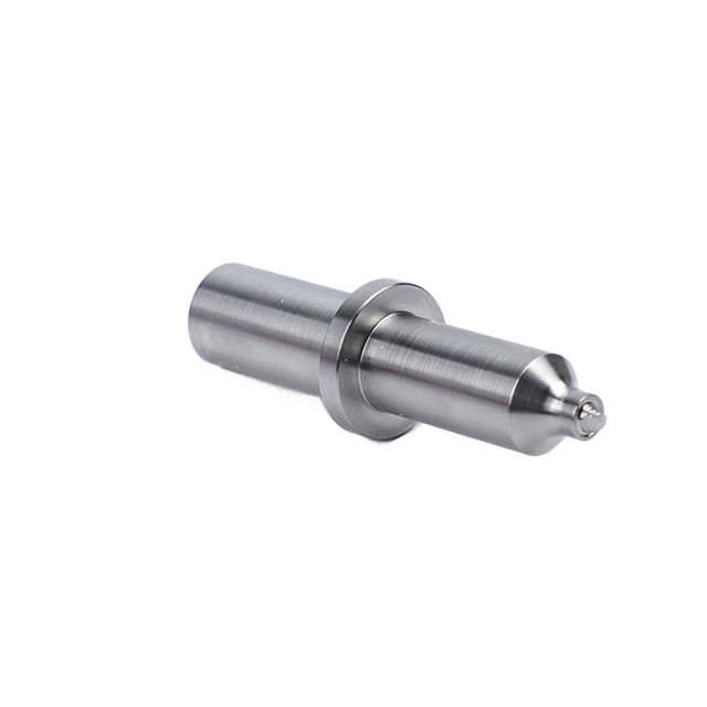
At the center of every friction stir welding machine is the FSW tool, a non-consumable component that directly controls heat generation, material flow, and final weld quality. Unlike fusion welding torches, the FSW tool physically interacts with the workpiece, which is why its design has such a strong influence on process stability and defect formation.
The shoulder is responsible for generating most of the frictional heat while also containing the softened material beneath it. A well-designed shoulder helps prevent material expulsion, improves surface finish, and ensures consistent forging pressure across the weld. Spiral or scroll shoulder designs are commonly used because they help drive material back toward the weld center, reducing flash and improving surface appearance, especially in long aluminum welds.
The pin or probe extends into the joint line and performs the actual stirring action. As it rotates, the pin mixes and transports plasticized material from the leading edge to the trailing edge of the tool, creating a solid-state bond. Pin length directly controls penetration depth, while pin diameter and profile influence material flow patterns and the likelihood of internal defects such as tunnel voids or lack of consolidation.
Different tool geometries are selected based on material type, thickness, and joint design. For example, cylindrical pins are often used for general-purpose aluminum welding, while threaded or tapered pins improve mixing in thicker sections. Poor tool geometry selection can lead to surface defects, excessive flash, or hidden internal flaws, even when machine parameters appear correct.
While the tool performs the welding action, overall weld quality depends heavily on the capabilities of the friction stir welding machine itself. One of the most decisive factors is axial force control, sometimes referred to as Z-axis force regulation. Maintaining a stable, controlled downforce ensures consistent material consolidation, especially when working with cast components or parts that have surface variation.
Precise control of spindle speed and traverse speed is equally important. Spindle speed governs heat input, while traverse speed determines how long heat is applied to a given section of the joint. The balance between these two parameters directly affects grain structure, surface appearance, and mechanical performance. Stable, synchronized control prevents overheating, underheating, and inconsistent weld profiles.
Structural rigidity is another critical factor that is often underestimated. Friction stir welding generates high process forces, and any deflection in the machine frame can lead to variations in plunge depth, uneven forging pressure, and reduced tool life. Rigid machine structures help maintain dimensional accuracy and minimize the risk of internal weld defects.
For quality-critical applications, temperature monitoring, data logging, and real-time feedback systems play an increasingly important role. By tracking process variables such as tool temperature, axial force, and torque, manufacturers gain better process visibility, enable traceability, and support qualification requirements in industries like aerospace and EV manufacturing.
Finally, fixturing and clamping systems are an essential but often overlooked part of the welding system. Because FSW relies on high axial force, workpieces must be rigidly clamped against a backing anvil to prevent lifting or movement. Inadequate fixturing can compromise weld quality regardless of how advanced the machine or tooling may be.
Dedicated friction stir welding machines are purpose-built systems designed to deliver maximum rigidity and high axial force. These machines are engineered specifically for FSW and are commonly used in production environments where weld quality, repeatability, and throughput are non-negotiable. Their robust structures allow them to handle thicker sections and high-strength aluminum alloys with stable process control.
This type of FSW machine is best suited for applications involving thick materials, demanding quality standards, and continuous production cycles, such as aerospace panels or structural EV components. The main trade-offs are a larger footprint and a more specialized role, as these systems are typically optimized for linear or planar welding paths rather than highly complex 3D geometries.
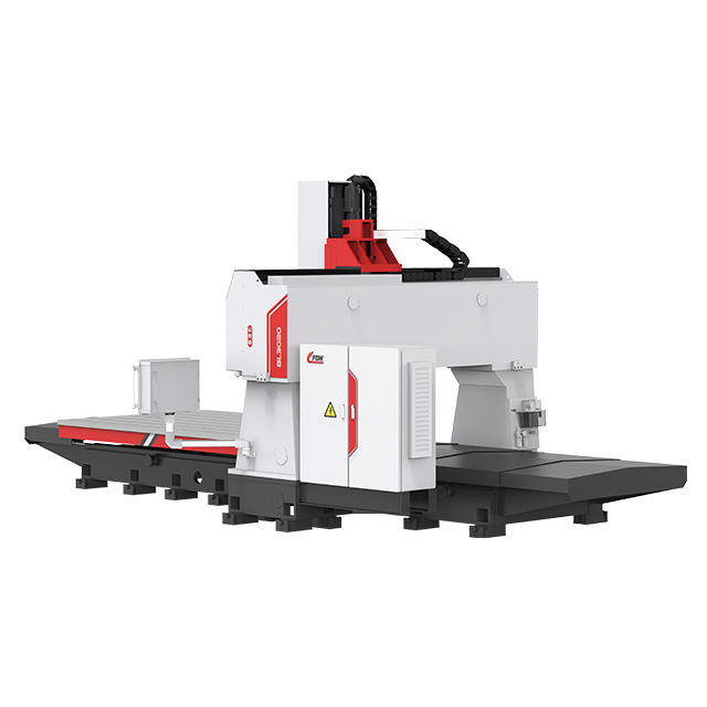
Gantry-type friction stir welding machines are built around a large, rigid frame that moves over a fixed workpiece. This configuration makes them ideal for long weld seams and large-format parts, where maintaining consistent force and alignment over extended distances is critical.
These machines are widely used for EV battery trays, chassis components, and large aluminum panels, which explains why gantry structures dominate many large-format EV manufacturing lines. Their ability to support heavy fixtures and large work envelopes while maintaining stiffness gives them a clear advantage in high-precision, large-scale applications.
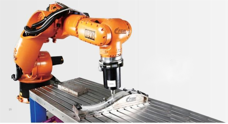
Robotic friction stir welding systems combine FSW tooling with multi-axis industrial robots, offering exceptional flexibility for complex 3D weld paths and reconfigurable production lines. They are especially useful when parts vary in shape or when welds cannot be performed on a single plane.
The trade-off comes in the form of reduced stiffness compared to dedicated or gantry machines. This can limit achievable thickness and accuracy, depending on the robot's force capability and structural support. As a result, robotic FSW is typically chosen for thinner materials and applications where flexibility and reach outweigh maximum welding force.
FSW heads designed for integration with existing CNC machines can provide a practical entry point into friction stir welding, particularly for R&D, prototyping, and low-to-medium volume production.
This approach is most suitable for relatively thin aluminum sections and short weld lengths, where process forces remain within the structural limits of the CNC platform. Performance is highly dependent on the machine's rigidity, spindle torque, and available axial force, which vary significantly between CNC models.
While CNC-integrated FSW solutions offer flexibility and fast deployment, they do not replace dedicated or gantry-type FSW machines in applications requiring high axial force, long continuous welds, or production-grade stability—such as EV battery trays, large panels, or thick die-cast aluminum components.
Compact and ultra-compact friction stir welding machines are designed for situations where space is limited or parts are small. These systems are commonly used for prototyping, laboratory work, and small EV components, where full-scale equipment would be impractical.
Despite their smaller size, compact machines still deliver the controlled force and motion required for quality FSW, making them a useful solution for development work or low-volume production in space-constrained workshops.
Multi-station friction stir welding systems are built for high-volume manufacturing environments where productivity is driven by parallel processing. By allowing multiple parts to be welded simultaneously or sequentially across stations, these systems significantly improve throughput.
They are often used for battery pack components and long aluminum parts in EV manufacturing, where consistent quality must be maintained at scale. Multi-station configurations are typically integrated into automated production lines to maximize efficiency.
| Machine Type | Typical Capability | 2D / 3D Welding | Accuracy (Typical) | Ideal Applications |
|---|---|---|---|---|
| Dedicated FSW Machine | High force, thick sections | 2D | High | Aerospace structures, thick aluminum, high-volume production |
| Gantry FSW Machine | Long seams, large panels | 2D | High | EV battery trays, chassis, large panels |
| Robotic FSW System | Flexible, complex paths | 3D | Moderate | Complex geometries, reconfigurable lines |
| CNC + FSW Head | Thin to medium sections | 2D | High | R&D, prototyping, hybrid machining |
| Compact FSW Machine | Small parts, limited space | 2D | High | Small EV parts, lab use |
| Multi-Station FSW System | Parallel high throughput | 2D | High | Battery packs, long components |
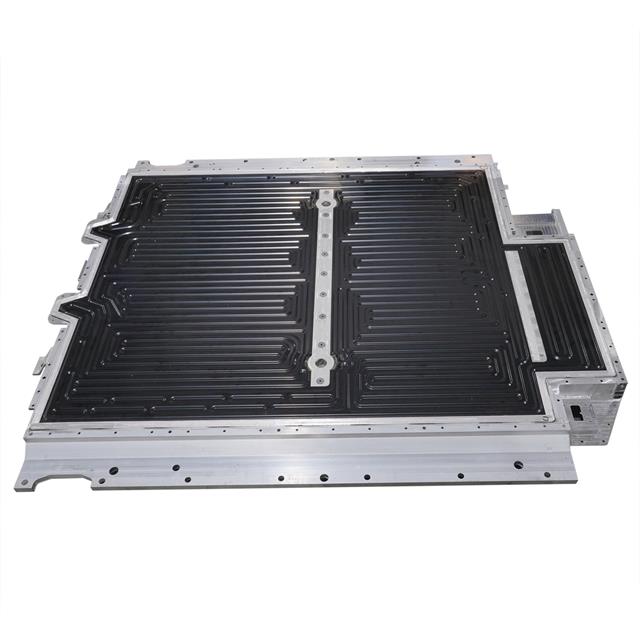
Electric vehicle manufacturing is currently the fastest-growing application area for friction stir welding, driven by the need for lightweight structures, high dimensional accuracy, and leak-tight joints. One of the most common uses is battery cooling plates, where flatness, internal channel integrity, and repeatability are critical. FSW produces smooth, fully consolidated seams that minimize distortion and reduce the risk of leakage in liquid-cooled systems.
Battery trays and enclosures are another major application. These components often require long, continuous welds on aluminum panels, where traditional welding would introduce excessive distortion. Friction stir welding allows manufacturers to maintain tight tolerances while achieving high structural strength, making it well suited for large-format EV battery systems.
FSW is also widely used for large die-cast EV structures, especially Al-Si alloys. These castings can vary in thickness and surface condition, which makes controlled force and stable heat input essential. In addition, heat exchangers and thermal management parts benefit from FSW's ability to create clean, defect-free joints without filler material.
In high-throughput EV production lines, dual-head or multi-head FSW configurations may be used to balance heat input or weld multiple seams simultaneously. This approach can improve cycle time and thermal symmetry, particularly on large battery components.
Outside of EV platforms, friction stir welding is increasingly applied to automotive body structures, subframes, and crash-relevant aluminum components. These parts demand high joint strength and consistent quality, especially in safety-critical zones where variability is unacceptable.
Joining cast aluminum components presents unique challenges due to material heterogeneity and silicon content. FSW addresses many of these issues by avoiding solidification defects, though proper tool material and force control are essential for stable results.
For visible exterior parts, exit-hole management becomes an important consideration. Manufacturers often rely on joint design strategies, run-off tabs, or advanced tooling such as retractable pin systems to minimize post-processing and maintain surface appearance.

In aerospace and defense manufacturing, friction stir welding is valued for its exceptional joint integrity and repeatability. Typical applications include fuselage panels, wing structures, and tanks or pressure vessels, where long weld seams must meet strict mechanical and fatigue requirements.
FSW is particularly well suited for high-strength aluminum alloys such as the 2xxx and 7xxx series, which are prone to cracking when fusion welded. Because the process operates below the melting point, it preserves material properties and produces fine-grained weld zones.
These industries are also heavily driven by compliance and qualification requirements. Process monitoring, data logging, and traceability are often mandatory, and FSW machines are commonly integrated into quality systems that support rigorous inspection and certification workflows.

Railway and transportation applications often involve long, linear welds on large aluminum panels, such as floors and sidewalls of train carriages. Friction stir welding delivers smooth, uniform seams that reduce the need for rework and post-weld finishing.
The low distortion achieved with FSW helps maintain dimensional accuracy over long weld lengths, which is especially important for modular assembly and consistent vehicle geometry. This makes the process well suited for both high-speed rail and urban transit manufacturing.
In marine and shipbuilding environments, friction stir welding is used for hull and deck panels made from corrosion-resistant aluminum alloys. Distortion control is a major value driver, as large panels must fit precisely during assembly.
FSW's solid-state nature minimizes residual stress and improves long-term structural performance in harsh marine conditions. The ability to produce clean welds with consistent mechanical properties makes it attractive for both commercial and specialized vessels.
Across industrial and energy sectors, friction stir welding is commonly applied to heat sinks, cold plates, and power enclosures, where thermal performance and joint reliability are critical. In some cases, copper busbars and hybrid aluminum-copper assemblies are joined using carefully controlled FSW processes.
The process is also used for large aluminum frames and structural assemblies in industrial equipment, where consistent weld quality and reduced distortion simplify downstream machining and assembly.
Emerging applications for friction stir welding include construction and architectural structures, such as large aluminum extrusions, bridge sections, and façade elements. These projects benefit from the process's ability to create strong, visually clean joints over long distances.
FSW is also gaining attention for dissimilar material joining in functional assemblies, particularly where electrical or thermal interfaces are required. By carefully managing tool position and process parameters, manufacturers can join materials with very different properties while maintaining reliable performance.
Aluminum is the most widely welded material using friction stir welding, covering virtually the full range from 1xxx to 7xxx series alloys. One of the key advantages of FSW is its ability to join high-strength aluminum grades, particularly 2xxx and 7xxx alloys, which are prone to hot cracking and porosity when fusion welded. Because FSW operates below the melting point, it preserves alloy chemistry and produces fine-grained, mechanically strong joints.
Cast aluminum alloys, especially Al-Si grades commonly used in automotive and EV structures, present additional challenges such as variable microstructure and higher abrasiveness. These materials typically require more robust tool materials and careful control of force and heat input to achieve stable, defect-free welds.
Magnesium alloys are increasingly used in lightweight applications due to their high strength-to-weight ratio. Friction stir welding is well suited to magnesium because the process minimizes oxidation and avoids the ignition risks associated with fusion welding. Typical applications include automotive components and aerospace structures where weight reduction is critical.
That said, magnesium alloys require careful process control, as they have a narrower processing window and lower melting temperatures. Proper tool design and conservative heat input are essential to maintain surface quality and prevent defects.
Copper and copper alloys are attractive for thermal and electrical applications, such as heat exchangers, power electronics, and busbars. Friction stir welding can successfully join copper, but the material's high thermal conductivity demands higher heat input and stable force control to maintain sufficient plasticization.
Tool material selection is especially important for copper welding. Tungsten-based or carbide tools are commonly used to withstand elevated temperatures and resist wear. Effective heat management, including optimized spindle speed and traverse rate, helps ensure consistent weld quality.
Titanium alloys are valued for their exceptional strength-to-weight ratio and corrosion resistance, particularly in aerospace and high-performance applications. Friction stir welding offers a solid-state alternative that reduces contamination risks and avoids many fusion-welding-related defects.
However, titanium welding requires a narrow and carefully controlled process window. Tool materials must withstand high temperatures and forces, and process parameters must be optimized to balance heat generation with tool life. As a result, titanium FSW is typically reserved for specialized, high-value components.
Steels and stainless steels can be friction stir welded, but they present higher technical demands compared to aluminum or magnesium. These materials require premium tool materials and significantly higher axial forces due to their strength and higher softening temperatures.
In practice, friction stir welding of steel is often limited to moderate thicknesses and lower traverse speeds to manage tool wear and process stability. Applications are usually focused on industrial or structural components where the benefits of solid-state joining justify the added complexity.
Friction stir welding also enables dissimilar metal joining, such as aluminum-to-copper, aluminum-to-steel, and aluminum-to-magnesium combinations. These joints are particularly valuable in applications that combine structural and functional requirements, like electrical or thermal interfaces.
The main challenge in dissimilar welding is controlling the formation of brittle intermetallic compounds. Techniques such as tool offset positioning, asymmetric pin designs, and precise force and heat control are commonly used to manage material flow and limit intermetallic growth while maintaining joint strength.
In friction stir welding, axial force is often the primary capability limiter. Unlike fusion welding, where heat input dominates, FSW relies on downward force to plasticize, consolidate, and forge the material beneath the tool. If the machine cannot maintain stable force, even perfectly chosen parameters will not prevent internal defects.
Different application families require very different force levels. Thin battery cooling plates typically need moderate, highly stable force to maintain flatness and leak-tightness. Battery trays and enclosures demand higher force over long weld lengths to control distortion. Thick die-cast aluminum components, especially Al-Si alloys, require the highest force levels to overcome material variability and ensure full consolidation.
| Application Type | Typical Force Demand | Key Risk if Undersized |
|---|---|---|
| Cooling plates | Low to medium | Incomplete bonding, leakage |
| Battery trays | Medium to high | Distortion, surface defects |
| Thick die-cast parts | High | Tunnel defects, lack of consolidation |
When force capability is insufficient, problems often appear beneath the surface. Common symptoms include internal tunnel defects, kissing bonds, inconsistent nugget formation, and reduced mechanical strength, even when the weld surface looks acceptable.
Spindle performance is defined not just by power, but by the combination of torque, speed range, and control stability. Torque plays a critical role when welding thicker sections or harder materials, as it directly affects the tool's ability to stir and move plasticized material.
High RPM alone does not indicate a capable FSW machine. In many demanding applications, adequate torque at lower rotational speeds is far more important than maximum speed. A spindle that delivers stable torque across a wide speed range allows better matching of heat input to material type, thickness, and joint configuration.
Matching the spindle envelope to the application helps avoid overheating, tool wear, and inconsistent weld quality. Thin aluminum sheets, thick extrusions, and cast components all require different torque–speed balances to remain within a stable process window.
Machine rigidity directly influences weld consistency, defect risk, and tool life. During friction stir welding, high axial and lateral forces are transmitted through the spindle and frame. Any structural deflection can lead to fluctuations in plunge depth and forging pressure.
Conceptually, C-frame designs offer compact layouts but may be more sensitive to deflection under high loads. Gantry structures provide excellent stiffness over large work envelopes, making them ideal for long seams and large panels. Box-type or heavy-frame designs maximize rigidity for high-force applications but often require more space and infrastructure.
A rigid structure not only improves weld quality but also extends tool life by reducing vibration and uneven loading on the tool.
In friction stir welding, accuracy is not just about positioning; it directly affects plunge depth stability and path tracking. Small deviations in tool position can change heat input, material flow, and forging pressure, leading to inconsistent weld properties.
Industry expectations vary. Aerospace applications typically demand very high repeatability to meet strict quality and fatigue requirements. General manufacturing may allow slightly wider tolerances as long as structural performance is consistent. Robotic FSW systems prioritize flexibility, accepting lower absolute accuracy in exchange for complex 3D path capability.
Understanding how accuracy translates into weld quality helps align machine capability with real production needs.
Control strategy plays a major role in how well an FSW machine handles real-world part variation. Position control maintains a fixed tool depth, which works well on flat, highly consistent parts. Force control adjusts tool position dynamically to maintain constant axial force, making it better suited for castings or parts with surface variation.
In many production environments, hybrid control systems combine both approaches. Position control provides baseline accuracy, while force feedback compensates for thickness variation, distortion, or fixture tolerance. This balance improves repeatability and robustness across varying part conditions.
As friction stir welding scales into quality-critical industries, process monitoring and data capture become increasingly important. Temperature monitoring at the tool or spindle provides insight into heat input and tool condition, helping prevent overheating or premature tool failure.
Data logging of parameters such as force, torque, speed, and temperature supports process traceability and qualification. These records are often required for aerospace, EV, and other regulated industries, and they enable continuous improvement by linking weld quality outcomes to actual process conditions.
The first step in choosing the right friction stir welding machine is to clearly define what you are actually welding. Start with the basics: material type, thickness range, joint design (butt, lap, or T-joint), total weld length, and overall part geometry. These factors directly influence the required axial force, spindle capability, and machine structure.
It's also important to consider the work envelope. Small, repeatable parts can often be handled by compact or CNC-integrated FSW solutions, while large assemblies such as battery trays or panels require gantry or dedicated machines with extended travel. Finally, think about weld path complexity. Straight 2D seams are well suited to rigid machines, while 3D curved paths may point toward robotic or multi-axis solutions.
FSW machine costs vary widely depending on structure, force capability, and automation level, so it's more useful to think in cost tiers rather than fixed prices. Entry-level solutions typically focus on flexibility and fast deployment, while higher-end systems prioritize throughput, rigidity, and long-term production stability.
When evaluating ROI, look beyond the initial purchase price. Friction stir welding eliminates filler wire and shielding gas, significantly reduces distortion, and often cuts post-weld machining and rework. Break-even calculations should consider annual weld volume, labor savings, scrap reduction, quality costs, and automation potential, not just equipment cost.
| Cost Driver | Impact on ROI |
|---|---|
| Consumables eliminated | Direct operating cost reduction |
| Reduced distortion | Less rework and machining |
| Automation capability | Lower labor cost per part |
| Scrap and defect reduction | Improved yield and consistency |
Once application and budget boundaries are clear, technical specifications become the primary filter. Focus on axial force capacity, spindle torque and power, machine rigidity, motion accuracy, and control strategy. These parameters determine whether a machine can consistently deliver acceptable weld quality for your parts.
Quality monitoring requirements should also be defined at this stage. Some applications require basic parameter control, while others demand data logging, traceability, and integration with inspection systems. Machines that cannot support these requirements may struggle to scale into regulated or high-volume production.
Practical constraints often narrow the final decision more than technical specifications. Floor space and foundation requirements can vary significantly between compact systems, gantry machines, and robotic cells. Safety enclosures, especially for robotic FSW, must also be considered early in the layout planning process.
Delivery and implementation timelines are another key factor. Some solutions can be deployed quickly, while others involve longer lead times and more extensive installation. Training requirements and internal technical readiness should be assessed realistically to ensure a smooth ramp-up.
Finally, consider how the FSW machine will fit into your operation over the next several years. Modular designs allow for future upgrades, such as additional monitoring, automation, or station expansion, without replacing the entire system.
In some environments, multi-purpose workflows that combine machining and welding on the same platform offer added flexibility and asset utilization. Choosing a solution that can evolve with changing product designs and production volumes helps protect long-term investment value.
Choosing the right friction stir welding tool material starts with understanding what you're welding and how much heat and force the process will generate. For most aluminum applications, H13 and other common tool steels are widely used because they offer a good balance of strength, heat resistance, cost, and tool life. They perform well across a broad range of aluminum alloys and are easy to maintain in production environments.
For higher-temperature or more abrasive materials, such as copper, stainless steel, or titanium, standard tool steels may wear too quickly. In these cases, carbide-based tools or premium materials such as PCBN or PCD are often required. These materials can withstand higher temperatures and stresses but come with higher cost and more limited operating windows.
Tool life is governed by a few critical factors:
Process temperature: Excessive heat accelerates wear and softening
Force stability: Fluctuating axial force increases mechanical fatigue
Material abrasiveness: Cast alloys and reinforced materials shorten tool life
| Workpiece Material | Common Tool Material | Relative Tool Life | Typical Use Case |
|---|---|---|---|
| Aluminum alloys | H13 tool steel | Long | General manufacturing |
| Cast aluminum (Al-Si) | Hardened steel / carbide | Medium | Automotive structures |
| Copper alloys | Carbide | Medium | Thermal and electrical parts |
| Steel / stainless steel | PCBN / PCD | Short | Specialized industrial parts |
| Titanium alloys | Premium tungsten-based | Short | Aerospace components |
Tool geometry plays a direct role in heat generation, material flow, and surface appearance. One of the first decisions is pin length, which is typically set slightly shorter than the material thickness to ensure full penetration without damaging the backing anvil. An undersized pin can lead to lack of consolidation at the root, while an oversized pin increases tool load and wear.
The shoulder diameter controls how much heat is generated and how well the softened material is forged. Larger shoulders produce more heat and better surface finish but also increase axial force requirements. Smaller shoulders reduce heat input but may struggle to contain material in thicker sections.
Joint type also influences geometry choices. Butt joints generally allow simpler pin profiles and symmetric flow, while lap joints require more aggressive stirring to move material across the interface. For many aluminum applications, spiral or scroll shoulder designs are preferred because they actively pull material back toward the weld center, reducing flash and improving consistency, especially on long seams.
For applications where surface appearance or functional integrity is critical, retractable pin tools are often used to eliminate or minimize exit holes at the end of the weld. These tools allow the pin to retract before tool withdrawal, making them useful for visible components or pressure-tight assemblies.
Temperature-sensing tools and smart tool holders add another layer of process control. By measuring tool or interface temperature in real time, manufacturers can better manage heat input, detect abnormal conditions, and support traceability requirements in regulated industries.
In more specialized cases, stationary shoulder tools are used to reduce surface heat and improve finish, particularly on curved or complex paths. Bobbin tools, which apply forging pressure from both sides of the joint, can be effective for certain plate and extrusion welds where double-sided access is available and consistent consolidation is required.
While friction stir welding is extremely versatile, it is not ideal for every material and thickness range. Ultra-thin sheets present a particular challenge because there is very little material available to generate and retain heat. Maintaining stable plunge depth without tearing, excessive thinning, or surface damage becomes difficult, especially at industrial production speeds.
At the other end of the spectrum, high-melting-point alloys such as certain steels, superalloys, or refractory metals can technically be friction stir welded, but tooling cost and wear often dominate the economics. These materials require premium tool materials and high axial force, which can significantly increase cost per meter of weld. In such cases, alternative processes like laser welding, electron beam welding, or hybrid approaches may offer a more practical balance between performance and cost.
FSW requires direct tool access along the entire joint path, which makes some part geometries inherently unsuitable. Closed profiles, internal corners, deep recesses, or enclosed cavities may prevent the tool shoulder from making proper contact with the surface, limiting the ability to generate heat and forging pressure.
Start and stop zones also require careful planning. Because the tool must plunge into and retract from the material, exit-hole placement becomes a design consideration. If these locations cannot be hidden, machined away, or managed through run-off tabs or advanced tooling, alternative joining methods may be preferable. In some cases, redesigning the joint or combining FSW with another welding process can resolve these limitations.
One of the most underestimated aspects of friction stir welding is fixture engineering. FSW generates significant axial force, and without rigid clamping and a properly designed backing anvil, weld quality will suffer regardless of machine capability or parameter selection.
Fixture design affects more than just quality. Heavy, complex fixtures increase setup time, restrict access, and can lengthen overall cycle time. Backing anvils must support the full welding load while maintaining flatness and alignment, especially for thin panels or long seams. If fixture complexity becomes excessive, manufacturers may find that alternative welding methods or a hybrid joining strategy provides a more efficient production solution.
Battery cooling plates place very specific demands on a friction stir welding system. Flatness, leak-tightness, and repeatability are usually more important than maximum thickness capability. Internal channels must remain sealed, and even small distortions can affect thermal performance or cause leakage during pressure testing.
For this type of application, high-precision gantry machines or dedicated flat-bed FSW systems are typically the best fit. These machine archetypes offer stable force control across long seams and excellent positional repeatability, which helps maintain uniform heat input and surface quality. In higher-volume production, multi-station or synchronized dual-head configurations may be used to improve throughput while keeping thermal balance under control.
EV battery trays, chassis components, and large structural panels usually involve long, continuous weld seams and relatively large part sizes. Here, the priorities shift toward machine rigidity and consistent axial force over distance, rather than compactness or flexibility.
In most cases, gantry-type FSW machines are preferred because they can span large work envelopes while maintaining stiffness. For especially demanding structural requirements or thicker sections, dedicated heavy-frame FSW machines may be selected. The choice often comes down to part size and production volume: gantry structures excel at large panels, while dedicated machines offer maximum force and stability for safety-critical components.
Thick die-cast aluminum parts, especially Al-Si alloys, introduce additional complexity due to material variability, porosity, and surface inconsistency. These applications typically require higher axial force and sufficient spindle torque to ensure full consolidation through the entire thickness.
Dedicated FSW machines with high force capacity and robust control systems are commonly used in this scenario. Closed-loop force control helps compensate for thickness variation, while rigid machine structures reduce the risk of internal defects. Typical risk points include tunnel defects, inconsistent penetration, and accelerated tool wear, all of which can be mitigated through stable force control, appropriate tooling, and conservative parameter selection.
For small parts, prototypes, or mixed-production environments, flexibility often outweighs maximum welding capacity. Compact FSW machines or CNC-integrated FSW heads are popular choices in R&D labs and job shops because they allow fast setup changes and efficient use of existing equipment.
These configurations are well suited for thinner materials and shorter welds, and they make it easier to experiment with parameters or new designs. In this context, the ability to switch between machining and welding, or to adapt quickly to new parts, can be more valuable than investing in a large, dedicated system.
Applications involving complex three-dimensional weld paths are where robotic friction stir welding shows its strongest advantages. Multi-axis robots allow the tool to follow curved or inclined joints that would be difficult or impossible on rigid 2D machines.
That said, robotic FSW comes with trade-offs. Reduced stiffness compared to gantry or dedicated machines limits achievable thickness and force, which can affect weld quality in demanding applications. Robotic systems perform best on thinner materials and moderate force levels, where flexibility and reach are more important than maximum rigidity.
| Application Scenario | Key Requirements | Recommended Machine Type |
|---|---|---|
| Battery cooling plates | Flatness, leak-tightness, precision | Gantry or precision dedicated FSW |
| Battery trays / large panels | Long seams, rigidity, repeatability | Gantry or heavy dedicated FSW |
| Thick die-cast aluminum | High force, stable control | Dedicated high-force FSW |
| Small parts / R&D | Flexibility, fast setup | Compact FSW or CNC + FSW head |
| Complex 3D paths | Multi-axis access | Robotic FSW system |
From an investment perspective, friction stir welding (FSW) changes the cost structure of welding rather than simply reducing one expense line. One of the most immediate savings comes from the fact that FSW requires no filler wire and no shielding gas, eliminating recurring consumable costs and the variability they introduce into the process.
FSW also significantly reduces the need for rework and post-weld machining. Because the process produces low distortion and consistent weld profiles, parts are more likely to meet dimensional requirements straight off the machine. This is especially valuable for large aluminum panels, battery trays, and cooling plates, where distortion correction can be both time-consuming and expensive.
Lower heat input translates directly into lower scrap rates. With fewer defects such as porosity, cracking, or lack of fusion, manufacturers see more stable yields and less material waste. Over time, this consistency often has a larger financial impact than the initial reduction in consumables.
Energy efficiency is another lever that is often overlooked. As a solid-state process, FSW typically consumes less energy per meter of weld than arc-based processes, particularly in long, continuous seams. Combined with faster effective cycle times—thanks to reduced setup, fewer inspections, and less downstream processing—this improves overall equipment efficiency.
| Cost Element | Traditional Welding | Friction Stir Welding |
|---|---|---|
| Consumables | High (wire, gas) | None |
| Distortion correction | Frequent | Minimal |
| Scrap and rework | Variable | Low and consistent |
| Energy per weld | Higher | Lower |
| Post-weld machining | Common | Often reduced or eliminated |
FSW investments make the most sense when evaluated in terms of meters of weld per year, rather than cost per part alone. Applications with long, repeatable weld seams—such as battery trays, cooling plates, and large structural panels—tend to reach break-even faster because savings accumulate with every additional meter welded.
Quality-driven ROI is another major factor. In applications where defects lead to high downstream costs—such as leak failures in battery cooling systems or warranty claims in structural components—the value of consistent, defect-free welds can quickly outweigh the initial equipment investment. Avoiding a small number of high-cost failures can justify FSW adoption on its own.
Automation further amplifies the return on investment. FSW is highly compatible with automated production, and as labor content per weld decreases, automation acts as a multiplier on cost savings. In high-volume environments, the combination of low consumable cost, stable quality, and automated operation is often what turns friction stir welding from a technical upgrade into a financially compelling manufacturing strategy.
One of the most common mistakes companies make is over-specifying machine capacity "just in case." It's tempting to choose the largest, most powerful friction stir welding machine to cover every possible future scenario, but this often leads to unnecessary capital expense, oversized footprints, and underutilized equipment. In reality, many applications—especially in EV and general manufacturing—fall well below the maximum force and thickness capabilities of heavy-duty systems. A better approach is to size the machine around real production requirements, with a reasonable margin rather than an extreme one.
Another frequent issue is underestimating material and tooling realities. Different materials behave very differently under friction stir welding, and tool life can vary dramatically depending on alloy composition, abrasiveness, and temperature. Assuming that one tool material or geometry will work across all applications often results in accelerated wear, unstable weld quality, or unexpected operating costs. Early material testing and tooling trials help avoid these surprises.
Many buyers also overlook the engineering effort required for fixturing and clamping. FSW generates high axial forces, and proper backing support and rigid fixtures are non-negotiable. Ignoring this workload can lead to delayed commissioning, poor weld quality, or longer cycle times than expected. In practice, fixture design should be considered part of the welding system, not an afterthought.
Focusing only on the purchase price instead of total cost of ownership (TCO) is another common pitfall. A lower upfront cost may be offset by higher consumable usage, shorter tool life, increased rework, or limited automation capability. Evaluating energy consumption, maintenance, tooling costs, and productivity over several years provides a much clearer picture of true investment value.
Finally, many teams underestimate the importance of qualification, documentation, and ramp-up planning. Friction stir welding may look simple once running, but stable production requires process validation, operator training, and often formal documentation—especially in regulated industries. Failing to plan for this phase can slow time-to-production and reduce confidence in the process, even when the equipment itself is well chosen.
A successful friction stir welding project starts with a structured feasibility study based on real parts, not assumptions. Sample trials should be performed on representative components using production-relevant materials, thicknesses, and joint designs. This phase focuses on exploring process parameters such as tool geometry, rotational speed, traverse speed, and axial force to identify a stable welding window.
Mechanical testing plays an important role at this stage. Depending on the application, this may include tensile testing, bend testing, or fatigue testing to verify that joint performance meets design requirements. The results from these trials also allow teams to refine ROI assumptions by replacing estimates with measured cycle times, tool life data, and quality outcomes.
Once feasibility is confirmed, attention shifts to defining the final equipment specification. This includes selecting the appropriate machine structure, force capacity, control system, and monitoring options based on the validated process requirements. Supplier evaluation at this stage should consider not only technical capability but also application support, service availability, and long-term upgrade options.
Facility preparation often runs in parallel with procurement. Power supply, foundations, safety enclosures, and material handling must be planned early to avoid installation delays. A realistic timeline that accounts for delivery, installation, and commissioning helps align internal resources and production planning.
Training is critical to achieving stable production. Operators and process engineers need a clear understanding of FSW fundamentals, machine operation, tooling setup, and basic troubleshooting. Unlike traditional welding, FSW relies heavily on force and motion control, so hands-on training is especially valuable.
In many industries, a process qualification mindset is required, even if formal WPS or PQR documentation is not mandated. Defining acceptable parameter ranges, documenting procedures, and integrating data capture into the quality system help ensure repeatability. Traceability setup, including parameter logging and inspection linkage, should be completed before full production begins.
Production typically starts with pilot runs to confirm stability under real operating conditions. During this phase, close attention is paid to tool wear, heat input consistency, and part-to-part variation. Early monitoring helps identify trends before they impact quality or throughput.
As confidence grows, parameters can be fine-tuned to improve cycle time, extend tool life, or reduce energy consumption. Friction stir welding lends itself well to continuous improvement, where data from production is used to refine the process over time and maintain consistent performance as volumes increase.
One of the most significant developments shaping the future of friction stir welding (FSW) is the rise of AI-driven monitoring and predictive maintenance. Modern FSW machines already collect large amounts of process data, such as force, torque, temperature, and spindle load. The next step is using this data intelligently. Machine learning models can identify subtle patterns that indicate tool wear, process drift, or impending defects, allowing maintenance or parameter adjustments before quality is affected. For manufacturers, this means higher uptime, more consistent weld quality, and reduced unplanned downtime.
Another important trend is hybrid heating assistance, particularly laser-assisted and induction-assisted friction stir welding. These approaches introduce an external heat source ahead of or around the tool to preheat the material. By reducing the mechanical load on the tool, hybrid FSW expands the practical welding window for harder materials, thicker sections, and higher welding speeds. This is especially relevant for steel, titanium, and advanced aluminum alloys where pure mechanical stirring alone may limit productivity or tool life.
FSW technology is also moving toward broader dissimilar material joining capabilities. As EVs, power electronics, and lightweight structures become more complex, manufacturers increasingly need to join materials with very different thermal and mechanical properties. Advances in tool design, force control strategies, and process optimization are making aluminum-to-copper, aluminum-to-steel, and other hybrid joints more reliable, opening new possibilities for functional and multi-material assemblies.
Interest in polymer and composite friction stir welding continues to grow, particularly for thermoplastics used in lightweight enclosures and structural components. While this area is still developing compared to metal FSW, early industrial applications show promise for joining reinforced plastics with minimal degradation and good surface quality. Practical adoption depends on material type, reinforcement content, and part geometry, but the technology is moving steadily from laboratory research into niche production use.
Finally, friction stir welding is increasingly positioned as a sustainable and green manufacturing process. Its low energy consumption, absence of consumables, and minimal emissions align well with corporate sustainability goals and regulatory pressure to reduce carbon footprints. As manufacturers measure and report environmental impact more rigorously, FSW's solid-state nature becomes not just a technical advantage, but a strategic one in long-term manufacturing planning.
A: Friction stir welding (FSW) works best on materials that can plasticize and “forge” under heat and pressure without melting. It is generally not suitable (or is impractical) for:
Brittle, non-forgeable materials that crack instead of flowing
Some very high-melting-point alloys where tooling wear/cost becomes excessive (FSW may be technically possible but not economical)
Certain material combinations that form brittle intermetallic layers too quickly (some dissimilar pairs) unless the joint design and process are carefully engineered
A: Industry references and industrial practice consistently emphasize FSW's strengths on aluminum alloys (including high-strength series) and its growing use on magnesium, copper, and in more specialized cases titanium and steels, provided the machine force/torque and tool material are appropriate. FSW is also used for dissimilar joints like Al–Cu and Al–Steel when intermetallic growth is controlled through offset and parameter strategy.
A: Thickness capacity depends mainly on axial force, torque, rigidity, and tooling, not just “FSW” as a label.
Single-pass: common for thin-to-medium sections in aluminum; thicker sections demand much higher force and torque
Multi-pass: used when single-pass capacity is exceeded or when controlling heat/flow is easier in steps
Double-sided (weld from both sides): used to extend thickness capability and improve root quality when access allows
In short: there isn't one universal max thickness—it's application- and machine-dependent, and this is why competitors stress machine rigidity/force and proper tooling selection.
A: Same answer as above: the practical limit is set by machine force + torque + stiffness + tool design and whether you can use double-sided or multi-pass strategies. For thick structural aluminum, dedicated high-force systems are typically chosen because they can maintain stable forging pressure through the entire weld depth.
A: The primary limiting factors are axial force capacity, available torque at low speed, machine stiffness, and tool durability. Insufficient capability can lead to internal defects such as tunnel voids or incomplete consolidation.
A: Friction Stir Welding (FSW) is a solid-state joining process in which a rotating, non-consumable tool generates frictional heat and mechanically stirs the material to form a forged joint. Unlike traditional welding, the base material does not melt, which significantly reduces distortion and eliminates solidification-related defects such as porosity and hot cracking.
A: FSW stands for Friction Stir Welding. The term refers to both the welding process itself and, by extension, the machines and tooling designed to perform this solid-state joining method.
A: FSW is known for producing high-strength, low-distortion welds with excellent repeatability. It is especially valued in aluminum-intensive industries for its ability to weld long seams, reduce post-weld machining, and maintain tight dimensional tolerances in production environments.
A: Friction stir welding is widely used for:
EV battery cooling plates, trays, and enclosures
Aerospace fuselage panels, tanks, and structural parts
Railway and marine aluminum panels
Industrial heat sinks, cold plates, and structural frames
These applications benefit from FSW's low heat input, strong joints, and high process stability.
A: Tool life varies significantly based on workpiece material and process stability. Aluminum alloys generally offer long tool life, while harder or more abrasive materials shorten it. Stable force control and proper temperature management are key to maximizing tool life.
A: Tool wear is mainly driven by:
Excessive process temperature
Fluctuating axial force
Material abrasiveness (e.g. cast aluminum, reinforced alloys)
Inappropriate tool material or geometry
A: Friction stir welding can require a higher initial equipment investment than basic arc welding, mainly due to machine rigidity and force control requirements. However, operating costs are often lower because there is no filler wire, no shielding gas, less distortion, and reduced rework. For long aluminum seams and quality-critical parts, FSW is often cost-effective over time.
A: Operating cost is influenced by:
Tooling cost per meter of weld
Energy consumption per cycle
Labor and automation level
Scrap and rework rate
Many manufacturers evaluate FSW economics using cost per meter of weld rather than cost per part, which better reflects long-seam applications.
A: FSW does not replace all traditional welding processes. It excels in applications requiring low distortion, high repeatability, and long aluminum welds. Traditional welding may still be preferred for very thin materials, complex access geometries, or localized repair work.
A: FSW performs particularly well for long aluminum seams, distortion-sensitive assemblies, and automated high-volume production, where consistent quality and dimensional stability are critical.
A: Traditional welding remains suitable for:
Ultra-thin sheet metal
Joints with limited tool access
Short, non-structural welds
Situations where fixturing requirements for FSW would be excessive
A: In a qualification-driven workflow, a Welding Procedure Specification (WPS) is defined first and then validated through testing documented in a Procedure Qualification Record (PQR). This approach is commonly adapted for FSW in regulated industries.
A: FSW is a force-dominated process. Stable axial force ensures consistent material consolidation and helps compensate for part thickness variation, especially in castings or large panels.
A: Insufficient rigidity allows deflection under load, leading to inconsistent plunge depth, uneven forging pressure, internal defects, and accelerated tool wear. High stiffness is essential for repeatable weld quality.
Before committing to a friction stir welding machine, it's worth stepping through a structured checklist to make sure nothing critical is overlooked. Start with the fundamentals: what materials you plan to weld and the full thickness range you expect, not just today but over the next few years. This directly impacts required force, tooling, and machine structure.
Next, look at weld length, part size, and motion requirements. Short seams on small parts point to very different solutions than long welds on large panels. Be clear on whether your application is primarily 2D linear welding or requires true 3D path capability, as this alone can narrow the field significantly.
Production expectations matter just as much. Define your annual weld meters and throughput targets, and consider whether current volumes justify automation or multi-station systems. At the same time, clarify quality and traceability standards, especially if you serve EV, aerospace, or other regulated markets where data logging and documentation are essential.
Budget planning should go beyond the purchase price. A realistic view of capex plus five-year total cost of ownership (TCO)—including tooling, maintenance, energy, and labor—will prevent surprises later. Facility constraints also need to be addressed early: available footprint, foundation strength, safety enclosures, and material handling flow can all influence which machines are practical.
Finally, assess readiness inside your organization. Consider delivery timelines, implementation capacity, internal expertise, and training needs. If you plan to weld dissimilar materials, make sure validation trials and tooling strategies are part of the plan, not an afterthought.
The right FSW solution often becomes clear when viewed through real-world scenarios rather than abstract specifications. For R&D environments, job shops, or low-risk entry into FSW, compact machines or CNC-integrated FSW heads are usually the most practical choice, offering flexibility and fast deployment with minimal infrastructure changes.
For EV battery cooling plate production, precision and repeatability are key. High-accuracy gantry or dedicated flat-bed FSW machines are typically preferred to maintain flatness, leak-tightness, and consistent weld quality at scale.
In the case of EV battery trays, chassis components, and large panels, long weld seams and structural demands point toward gantry-type or heavy dedicated FSW machines that can deliver consistent force and rigidity across large work envelopes.
Aerospace or other compliance-driven manufacturing environments generally favor dedicated FSW machines equipped with robust monitoring and traceability features, supporting qualification, documentation, and long-term process stability.
For complex 3D geometry production, robotic friction stir welding systems are often the best fit, provided material thickness and force requirements stay within realistic limits. In these applications, flexibility and reach outweigh maximum rigidity.
| Application Scenario | Typical Priority | Commonly Chosen FSW Solution |
|---|---|---|
| R&D / Job shop | Flexibility, fast setup | Compact FSW or CNC + FSW head |
| EV cooling plates | Precision, flatness | Gantry or precision dedicated FSW |
| Battery trays / large panels | Long seams, rigidity | Gantry or heavy dedicated FSW |
| Aerospace manufacturing | Traceability, consistency | Dedicated FSW with monitoring |
| Complex 3D paths | Flexibility, reach | Robotic FSW system |


