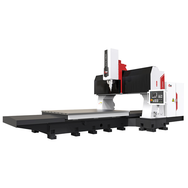
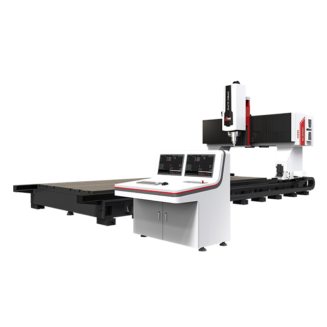
Zhihui develops customized friction stir welding equipment for aluminum vacuum chamber manufacturing, with machine configurations engineered around chamber dimensions, weld paths, fixturing and production requirements.
Our real project experience includes an open horizontal mirrored FSW system with dual 6000 mm X-axis travel, dual spindles and dedicated multi-axis capability for large aluminum vacuum chamber structures.
Large aluminum vacuum chambers can combine long weld seams, large structural panels and precision-machined interfaces in a single assembly. For these components, the welding equipment must do more than move an FSW tool along a programmed path. Machine rigidity, workpiece support, tool accessibility, fixturing and welding sequence all influence the final manufacturing result.
Zhihui develops friction stir welding machines for aluminum vacuum chambers based on the actual chamber dimensions, joint design, weld path and production requirements.
Rather than adapting every project to one standard machine platform, we evaluate the complete welding application before defining the machine structure, working envelope, axis travel, spindle configuration, fixture concept and FSW process.
For other aluminum production applications, explore our friction stir welding machines for EV and industrial aluminum applications.
Vacuum chamber manufacturing is not only a welding-process problem. Large aluminum structures must remain accurately positioned and adequately supported while welding loads are transferred through the tool, workpiece and fixture system.
Machine configuration therefore needs to be evaluated together with chamber dimensions, material thickness, weld length, joint geometry, tool accessibility, backing support, fixture rigidity and the dimensional requirements of the finished assembly.
This becomes especially important for long or multi-sided chambers. A machine with sufficient nominal travel may still be unsuitable if the fixture, chamber walls, flanges or other structural features restrict tool access or do not provide adequate support along the complete weld path.
For this reason, Zhihui treats the FSW machine, fixture, tooling and welding process as one integrated manufacturing system.
Friction stir welding is a solid-state joining process. The rotating FSW tool generates frictional heat and plastic deformation without creating a conventional molten weld pool.
For suitable aluminum vacuum chamber structures, this offers several manufacturing advantages.
Manufacturing Requirement
How FSW Helps
Distortion control | Solid-state joining and localized process heat can help reduce thermal distortion compared with many conventional fusion-welding processes. |
Fusion-related defect control | Without a conventional molten weld pool, FSW avoids solidification cracking and weld-pool porosity associated with fusion welding. |
Long weld seams | CNC-controlled motion supports long continuous welding paths when machine travel, backing support and fixturing are properly designed. |
Process repeatability | Rotation speed, travel speed, tool position and welding sequence can be controlled through the programmed FSW process. |
Production implementation | Once the fixture and welding process have been validated, the same manufacturing approach can be transferred into repeat production. |
FSW should not be treated as an automatic guarantee of a defect-free or leak-free chamber. Incorrect parameters, insufficient penetration, poor joint fit-up or inadequate fixturing can still create welding defects. Equipment capability and process validation therefore remain critical.
For a broader technical explanation of aluminum alloys, process behavior and FSW fundamentals, read our aluminum friction stir welding guide.

For a large aluminum vacuum chamber application, Zhihui developed an open horizontal mirrored FSW equipment configuration with two sets of motion axes and dual spindle systems.
The machine architecture was developed around the actual chamber geometry and long welding paths instead of forcing the component into an existing standard machine configuration.
The representative system provides 6000 mm X-axis travel on both X1 and X2 axes, 1800 mm travel on both Y axes and 600 mm travel on both Z axes. Two spindle systems provide speeds up to 1500 rpm, while B-axis adjustment and C-axis rotation expand tool positioning capability for the required welding layout.
The complete machine occupies approximately 9000 × 4000 × 3000 mm and has an approximate total weight of 30 tonnes, demonstrating the structural scale required for this particular large-format application.

The specifications below come from the real large-format vacuum chamber FSW project described above.
This is a project reference rather than a fixed standard machine specification. Final machine dimensions, working envelope, spindle configuration and fixture layout are determined according to each customer's actual chamber drawing, weld path and production requirements.
Specification
Project Configuration
Machine Structure | Open horizontal mirrored configuration |
Approx. Machine Footprint | 9000 × 4000 × 3000 mm |
Working Table Width | 1900 mm |
Workpiece Width for Mirrored Welding | 650–1750 mm |
X1 Axis Travel | 6000 mm |
X2 Axis Travel | 6000 mm |
Y1 Axis Travel | 1800 mm |
Y2 Axis Travel | 1800 mm |
Z1 Axis Travel | 600 mm |
Z2 Axis Travel | 600 mm |
B1 / B2 Axis Adjustment | ±5° (manually adjustable) |
C1 / C2 Axis Rotation | ±360° |
X1 / X2 Axis Travel Speed | 0–10,000 mm/min |
Y1 / Y2 Axis Travel Speed | 0–5,000 mm/min |
Z1 / Z2 Axis Travel Speed | 0–3,000 mm/min |
C1 / C2 Axis Rotation Speed | ≤10 rpm |
Spindle 1 / Spindle 2 Speed | ≤1500 rpm |
X-Axis Positioning Accuracy | 0.05 mm/m |
X-Axis Repeat Positioning Accuracy | 0.05 mm/m |
Y-Axis Positioning Accuracy | 0.05 mm/m |
Y-Axis Repeat Positioning Accuracy | 0.05 mm/m |
Z-Axis Positioning Accuracy | 0.05 mm over full travel |
Z-Axis Repeat Positioning Accuracy | 0.05 mm over full travel |
Approx. Total Power | 110 kW |
Approx. Machine Weight | 30 t |
Large vacuum chamber structures can require welding access along opposing sides or long parallel joint paths. For this project, the mirrored machine layout provides two sets of motion axes and two spindle systems within one dedicated large-format FSW platform.
The configuration allows the machine architecture to match the actual chamber width and weld locations while providing the structural support and working space required by the welding application.
For the representative machine, chamber widths from approximately 650 to 1750 mm can be accommodated for the specified mirrored welding arrangement.
This architecture is application-specific. A smaller vacuum chamber or a different weld layout may require a simpler configuration, while larger or more complex components may require further customization.
Fixturing is one of the most important elements of vacuum chamber friction stir welding.
During FSW, the workpiece must be supported against welding loads while close joint fit-up is maintained throughout the weld path. The fixture therefore needs to work together with the machine rather than being treated as a separate accessory.
Fixture development typically considers backing support beneath the weld, clamping position and spacing, chamber panel stiffness, joint fit-up, prevention of local lifting or separation, tool clearance, welding sequence and practical loading and unloading.
For precision vacuum structures, fixture planning should also consider the relationship between welding deformation, machined surfaces, flange positions, sealing interfaces and downstream machining operations.
Machine capability alone does not determine weld quality. FSW tool geometry, tool penetration, rotation speed, travel speed, joint fit-up, material condition and fixture rigidity interact as one process system.
Zhihui develops application-specific friction stir welding tools according to the aluminum material, thickness, joint design and production conditions.
Rather than using one universal parameter set for every chamber, process parameters should be established and validated for the actual component and acceptance requirements.
The final welding process can then be evaluated against the customer's dimensional, structural and vacuum-related inspection criteria.
The suitability of FSW depends on joint accessibility, material thickness, backing conditions and the overall component structure.
Applications that can be evaluated include rectangular aluminum vacuum chambers, large welded chamber bodies, chamber cover structures, long linear aluminum assemblies, machined chamber structures with welded sections and other custom precision aluminum vacuum components.
For complex parts, the drawing should be reviewed before selecting the machine structure because chamber geometry may determine whether a standard, modified or fully customized FSW system is the most practical solution.
There is no single FSW machine specification suitable for every aluminum vacuum chamber.
A smaller component may fit an existing machine platform. A large chamber with long opposing weld paths may require extended travel, additional clearance, dual spindle systems, rotary axes or a dedicated equipment architecture similar to the project shown on this page.
Production requirements also influence machine selection. Prototype or low-volume manufacturing may prioritize fixture flexibility and accessibility, while repeat production may place greater emphasis on loading, welding sequence, process repeatability and automation integration.
This is why Zhihui begins equipment selection from the customer's workpiece and manufacturing requirements rather than simply recommending the largest available machine.
Project Information
What to Provide
Chamber Drawing | 2D drawing and 3D model if available |
Overall Dimensions | Length, width and height |
Material | Exact aluminum alloy and temper |
Material Thickness | Thickness at each FSW joint |
Joint Configuration | Butt, lap, cover or other joint design |
Weld Path | Location, direction and length of each required FSW seam |
Critical Dimensions | Flatness, position or machining tolerances that must be controlled |
Vacuum Requirement | Customer-defined vacuum or leak-test acceptance criteria |
Production Requirement | Prototype, small-batch or production volume |
Automation Requirement | Loading, unloading, positioning or production-line integration requirements |
Zhihui combines FSW equipment development with practical welding application experience. This allows the machine architecture to be developed around the real component instead of being selected only from a standard specification sheet.
A vacuum chamber equipment project can progress through:
Application evaluation → equipment configuration → fixture design → FSW tooling → process development → welding validation → production implementation
This engineering approach is particularly important for large chamber structures where machine travel, tool access, fixturing and welding sequence must be considered together.
Our vacuum chamber equipment capability is supported by an actual large-format aluminum chamber project using an open horizontal mirrored structure, dual spindle systems and 6000 mm X-axis travel on both sides.
We do not limit vacuum chamber projects to one standard machine structure. Working envelope, axis configuration, spindle arrangement and fixture requirements are evaluated according to the actual chamber.
A successful FSW system depends on more than the machine itself. We evaluate equipment architecture, fixturing, FSW tooling and process development together.
From drawing review and welding evaluation to final equipment configuration, our objective is to help manufacturers establish a practical and repeatable vacuum chamber FSW production capability.
Explore our broader friction stir welding applications for EV, thermal management and industrial aluminum manufacturing.
The appropriate machine depends on the chamber dimensions, aluminum material, thickness, weld path, joint design, fixture requirements and tool accessibility. Large chambers with long weld seams may require a customized large-format or multi-axis FSW system rather than a standard machine platform.
Yes. Machine travel can be evaluated according to the actual component. The real vacuum chamber project shown on this page uses 6000 mm travel on both X1 and X2 axes. Different or larger requirements should be evaluated from the customer's drawing.
The dual-spindle mirrored configuration was developed for the geometry and weld layout of this particular large vacuum chamber project. It provides two sets of motion axes and spindle systems within one dedicated machine architecture. Not every vacuum chamber requires this configuration.
No welding process alone should be treated as an unconditional guarantee of final vacuum performance. Leak-tightness depends on chamber design, joint preparation, welding process control, machining, sealing interfaces and final inspection. The FSW process should therefore be validated against the customer's specified acceptance criteria.
Yes. Fixture and FSW tooling requirements can be evaluated together with the equipment configuration according to the workpiece geometry, aluminum material, thickness and weld path.
Yes. Machine structure, working envelope, axis travel, spindle arrangement, fixture layout and other application-specific requirements can be evaluated according to the vacuum chamber and production plan.
Please provide the chamber drawing, overall dimensions, aluminum alloy and temper, material thickness, weld locations, critical dimensional requirements, vacuum or leak-test criteria and expected production volume.
Planning to manufacture aluminum vacuum chambers using friction stir welding?
Send us your chamber drawing, dimensions, material, weld path and production requirements. Our engineering team will evaluate the application and recommend a suitable machine structure, working envelope, fixture concept and FSW process solution.
Send Your Drawing for Equipment Evaluation