Views: 0 Author: Site Editor Publish Time: 2026-03-23 Origin: Site
Quick Answer: Friction stir welding copper can produce high-quality solid-state joints.
However, due to copper's high thermal conductivity, stable welding requires precise heat input control, optimized tooling, and a high-performance FSW machine.
Friction stir welding of copper is widely used in applications where high electrical conductivity, thermal performance, and structural reliability are required.
Typical applications include:
Electrical bus bars
Heat exchangers
Power distribution components
Electronics and semiconductor parts
Copper-aluminum dissimilar joints
These applications demand stable welding quality and minimal defects in production environments.
Copper presents a narrow processing window because rapid heat dissipation limits the time available for sufficient plasticization. This directly affects material flow stability and increases sensitivity to defects.
Key challenges include:
High thermal conductivity leading to insufficient heat retention
Reduced plasticization causing unstable material flow
Increased risk of tunnel defects and voids
Tool wear due to higher required loads and temperatures
In dissimilar welding, brittle intermetallic compound (IMC) formation
In engineering terms, thermal loss is not just a material property—it is a process-limiting factor in copper FSW.
Copper's exceptionally high thermal conductivity is one of the primary reasons why FSW parameter control is more difficult than in lower-conductivity alloys. Heat generated at the tool-workpiece interface is rapidly transferred away from the stir zone, which reduces the time available for sufficient softening and plastic flow. If the heat input is too low, inadequate plasticization may lead to tunnel defects, voids, or incomplete consolidation. If it is too high, grain coarsening, local softening, and reduced joint efficiency may occur. For this reason, heat input control is a central requirement in copper FSW process development.
In dissimilar copper-to-aluminum friction stir welding, interfacial intermetallic compound formation remains a major metallurgical concern. Excessive growth of brittle IMC layers can sharply reduce ductility, fatigue performance, and long-term joint reliability. Process design must therefore focus on limiting interfacial reaction thickness while still maintaining sufficient mixing and metallurgical bonding. This requires careful coordination of rotational speed, travel speed, tool offset, and thermal exposure time.
During friction stir welding copper, the microstructure undergoes dynamic recrystallization, leading to grain refinement in the stir zone. However, the rapid heat dissipation can cause uneven temperature gradients, affecting recrystallization kinetics. This may result in heterogeneous grain sizes and mechanical property variations across the weld. Achieving uniform microstructure requires precise process optimization.
Typical weld discontinuities in copper FSW include voids, tunnel defects, kissing-bond conditions, and occasional cracking under unfavorable thermal or metallurgical conditions. These defects are usually associated with insufficient plastic flow, incomplete consolidation, improper plunge condition, or an unbalanced combination of rotational speed and travel speed. Because copper dissipates heat rapidly, the process is especially sensitive to parameter combinations that fail to maintain a stable stirred volume through the full weld thickness. Defect prevention therefore depends on coordinated control of tool geometry, penetration depth, axial force, and heat input.
Although friction stir welding generates lower thermal input than fusion welding, copper’s high thermal conductivity and expansion coefficient can still cause residual stresses and distortion. These stresses may lead to warping or dimensional inaccuracies, especially in thin sections. Employing suitable clamping and controlled cooling strategies can reduce these issues.
Joining copper alloys to aluminum alloys introduces complexities such as differing melting points, thermal conductivities, and chemical affinities. The tendency to form brittle IMCs and the mismatch in mechanical properties demand tailored welding parameters and tool designs. Friction stir welding’s solid-state nature helps minimize these problems but requires careful process control.
Different copper alloy grades, such as oxygen-free copper, tellurium copper, or brass, exhibit varying weldability due to their composition and mechanical properties. For example, alloys with higher strength or alloying elements may require higher heat input or specialized tooling. Understanding the specific grade characteristics guides the selection of optimal friction stir welding copper parameters.
Tip: To overcome copper welding challenges, prioritize precise heat input control and select tool materials compatible with copper’s high thermal conductivity to ensure defect-free, high-quality welds.
Copper welding challenges are not only material-related. In production, they also depend heavily on machine stability, force control, tool design, and thermal management. If you are evaluating a more reliable solution for copper or copper-alloy welding, our friction stir welding equipment can help support better process control and joint consistency. Contact us to discuss your specific welding requirements.
Copper friction stir welding is fundamentally a thermo-mechanical process in which frictional heat generation, plastic deformation, and material flow interact to determine joint formation, microstructure evolution, and final mechanical properties.
Material flow in friction stir welding copper is primarily driven by the rotating tool’s pin and shoulder. The shoulder generates frictional heat and forges the softened copper, while the pin stirs and mixes the material beneath the surface. Copper’s high thermal conductivity demands efficient heat generation and material stirring to ensure proper plasticization and consolidation.
During welding, copper flows in a layered manner around the pin, with material from the retreating side transported toward the advancing side. The shoulder’s scrolled or spiral features help direct material flow inward, minimizing flash and surface defects. Proper material flow prevents common friction stir welding copper defects such as voids, tunnels, and cracks.
The tool pin penetrates the copper alloy, mechanically stirring the material and breaking up oxide layers. Its geometry—cylindrical, tapered, or threaded—affects the intensity and pattern of material mixing. For copper, cylindrical or tapered pins with threads or flutes are preferred to enhance stirring without excessive heat input.
The shoulder contacts the copper surface, generating most of the frictional heat. A flat or slightly convex shoulder with spiral features promotes uniform heat distribution and material flow. This balance is crucial given copper’s rapid heat dissipation, ensuring the weld zone remains plasticized for effective stirring.
Friction stir welding copper produces distinct microstructural zones:
Stir Zone (SZ): The central region where intense plastic deformation and dynamic recrystallization occur, leading to fine, equiaxed grains. Grain size can be reduced significantly, enhancing strength and ductility.
Thermomechanically Affected Zone (TMAZ): Surrounds the SZ and experiences plastic deformation with elevated temperatures but less intense stirring. Grain structure here is partially refined.
Heat-Affected Zone (HAZ): Adjacent to the TMAZ, it undergoes thermal cycles without plastic deformation, causing possible grain growth or phase changes.
For copper alloys, the SZ typically exhibits refined grains due to rapid recrystallization, while the HAZ may show slight softening from grain coarsening.
Dynamic recrystallization in the SZ refines copper grains from tens of microns down to a few microns or less. Rapid cooling techniques, such as liquid nitrogen spray, can further reduce grain size, improving hardness and tensile strength. However, excessive heat input may cause grain growth, reducing mechanical performance.
Recrystallization also homogenizes the microstructure, eliminating defects related to casting or prior deformation. This uniformity contributes to improved friction stir welding copper joint quality.
Fine-grained microstructures in the SZ correlate with enhanced mechanical properties such as increased strength, ductility, and toughness. The elimination of casting defects and oxide layers through effective stirring further improves joint integrity.
However, improper process parameters leading to incomplete recrystallization or excessive heat can degrade properties. For example, grain coarsening in the HAZ reduces hardness and may cause soft zones prone to failure under stress.
Copper alloys containing elements like zinc (brass), tin (bronze), or nickel exhibit varied microstructural responses during friction stir welding. Alloying elements can influence recrystallization kinetics, grain boundary stability, and the formation of secondary phases.
For instance, in brass alloys, friction stir welding promotes the redistribution of zinc, affecting hardness and corrosion resistance. Control of process parameters is essential to manage these effects and avoid brittle intermetallic compounds that could impair joint performance.
Tip: To optimize material flow and microstructural evolution in friction stir welding copper alloys, select tool geometries that promote uniform stirring and apply controlled cooling to refine grains and enhance joint mechanical properties.
Defect Type | Likely Cause | Recommended Solution |
|---|---|---|
Tunnel defects | Low heat input / poor plasticization | Increase rotation speed, optimize tool design |
Voids | Inadequate material flow | Adjust travel speed and plunge depth |
Flash formation | Excessive heat input | Reduce rotational speed or plunge |
Tool wear | Inadequate tool material | Use WC-Co or advanced alloys |
IMC formation (Cu-Al) | Excessive thermal exposure | Reduce heat input and optimize interface control |
Tool design is a primary process variable in copper FSW because it directly governs frictional heat generation, plastic flow behavior, forging pressure, and defect sensitivity. Since copper extracts heat rapidly from the tool-workpiece interface, both tool material and tool geometry must be selected to maintain thermal efficiency while resisting wear, thermal fatigue, and chemical interaction with the workpiece.
FSW tools for copper alloys require:
High wear resistance to endure abrasive contact with copper and prevent premature tool failure.
Thermal stability to maintain strength and dimensional accuracy at elevated temperatures.
Chemical compatibility to avoid harmful reactions with copper that could degrade the tool or weld quality.
Optimized geometry to facilitate effective stirring and minimize defect formation.
Copper welding often employs several tool materials:
Tool steels (e.g., H13, HSS): Widely used due to good toughness and thermal fatigue resistance. Suitable for thin to medium-thickness copper alloys.
Tungsten carbide-cobalt (WC-Co): Offers excellent wear resistance and hardness, ideal for prolonged welding of copper alloys. However, WC-Co tools can degrade at high temperatures due to cobalt binder softening.
Nickel-based alloys: Provide superior chemical compatibility with copper, reducing tool wear and contamination. Often used for specialized applications.
Composite materials (e.g., PCBN): While more common in harder alloys, some composites are adapted for copper to balance wear resistance and toughness.
Tool design significantly impacts weld quality:
Shoulder: Usually flat or slightly convex to generate sufficient frictional heat and contain plasticized copper. Scrolled or spiral shoulders improve material flow toward the pin, reducing flash and defects.
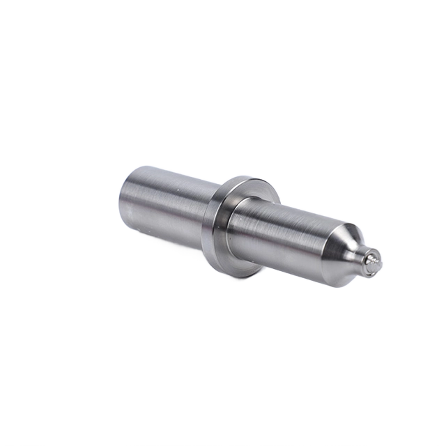
Pin: Typically cylindrical or tapered with threads or flutes to enhance stirring and mixing. Pin length must be carefully matched to copper sheet thickness to avoid voids or insufficient bonding.
Copper's high thermal conductivity demands tools that resist thermal fatigue cycles. Repeated heating and cooling can cause cracks or dimensional changes in the tool. Materials like WC-Co and Ni-alloys provide better thermal fatigue resistance compared to conventional steels. Regular monitoring of tool wear is essential to maintain consistent friction stir welding copper joint quality.
Chemical interaction between tool and copper can lead to tool degradation and weld contamination. For example, carbon diffusion from carbide tools into copper may affect weld properties. Selecting tool materials with minimal solubility or reactivity with copper reduces such risks.
Recent advances include:
Retractable pin tools: Eliminate exit holes, improving surface finish and reducing post-weld machining.
Real-time temperature sensing: Embedded sensors in tools enable precise thermal control, optimizing friction stir welding copper parameters.
Stationary shoulder FSW (SSFSW): Employs a non-rotating shoulder with a rotating pin, reducing surface defects and tool wear.
Tool life depends on material, welding parameters, and maintenance:
Implement regular inspections for wear and damage.
Use cooling systems to manage tool temperature.
Optimize welding parameters to reduce excessive heat and mechanical stress on tools.
Schedule timely tool replacement to avoid weld defects caused by worn tools.
Tip: For friction stir welding copper alloys, choose tool materials with high wear resistance and chemical compatibility, and optimize tool geometry to balance heat generation and material flow for defect-free welds.
In copper FSW, process optimization is essentially the control of a narrow thermo-mechanical window. Rotational speed, travel speed, plunge depth, tilt angle, and axial force interact to determine heat input, material plasticization, and consolidation quality. Because copper dissipates heat quickly, parameter combinations that work well for aluminum cannot be transferred directly without adjustment.
Rotational speed and welding speed directly affect heat generation and material flow during friction stir welding copper alloys. Higher rotational speeds increase heat input, improving plasticization but risking grain coarsening if excessive. Conversely, low rotational speeds might lead to insufficient heat, causing voids or tunnels.
For commercially pure copper sheets around 2–3 mm thick, optimal rotational speeds typically range between 600 and 1600 rpm. Welding speeds often vary from 150 to 200 mm/min for thin sheets, balancing heat input and productivity. For thicker copper alloys (e.g., 5–6 mm), rotational speeds may reach up to 10,000–14,000 rpm, with welding speeds adjusted accordingly to avoid overheating or incomplete bonding.
Fine-tuning the ratio of rotational speed to welding speed—sometimes expressed as specific thermal contribution—helps maintain a stable weld temperature and sound joint quality. For instance, studies show that maintaining ω⊃2;/v (rotational speed squared over welding speed) above a threshold ensures defect-free welds in copper alloys.
The tool tilt angle, generally set between 2° to 3°, enhances downward forging pressure and improves material consolidation behind the tool. A slight tilt promotes better material flow and reduces surface defects like flash or voids.
Plunge depth must be carefully matched to the copper sheet thickness. Insufficient plunge depth can cause lack of bonding or root defects, while excessive plunge depth risks tool damage or excessive flash. For copper alloys, plunge depths slightly less than the sheet thickness are preferred to avoid tool shoulder contact with the backing plate.
Given copper's rapid heat dissipation, thermal management is critical. Techniques include:
Active cooling: Spraying liquid nitrogen or CO₂ on the weld surface to rapidly cool and refine grains.
Submerged welding: Underwater friction stir welding to control heat input and microstructure.
Back-side heating: Applying controlled heat beneath the joint to reduce thermal gradients and improve material flow.
These methods help achieve finer grain structures, reduce residual stresses, and enhance mechanical properties.
Rapid cooling methods, such as cryogenic sprays, can reduce grain size in the stir zone to as low as 2 µm, significantly improving strength and hardness. Controlled cooling also prevents excessive grain growth in the heat-affected zone, preserving joint toughness.
However, overly aggressive cooling may induce thermal stresses or cracking. Therefore, cooling rates must be optimized based on alloy grade and thickness.
Thin sheets (1–3 mm): Rotational speeds of 600–1600 rpm; welding speeds of 150–200 mm/min; tilt angle of ~3°; plunge depth just below sheet thickness.
Medium thickness (4–6 mm): Higher rotational speeds up to 10,000 rpm; welding speeds adjusted between 40–150 mm/min; careful thermal management essential.
Thick sections (>6 mm): Specialized tooling and process control needed; potential use of double-sided FSW or advanced pin designs.
Maintain adequate heat input by balancing rotational and welding speeds.
Use proper tool tilt angle to enhance material forging and flow.
Optimize plunge depth to ensure full joint penetration without tool damage.
Employ cooling techniques to control microstructure without inducing thermal stresses.
Monitor welding forces and temperatures in real-time to adjust parameters dynamically.
Tip: For friction stir welding copper, carefully balance rotational and welding speeds while using a slight tool tilt angle and precise plunge depth to optimize heat input and material flow, minimizing defects and ensuring superior joint quality.
Achieving superior friction stir welding copper joint quality requires a combination of meticulous preparation, proper tool and process parameter selection, and effective monitoring. Copper’s high thermal conductivity and unique alloy behaviors demand tailored best practices to ensure defect-free, strong welds.
Surface cleanliness: Remove oxides, oils, and contaminants to promote good material flow and bonding.
Joint fit-up: Ensure tight clamping and minimal gaps to avoid voids or tunnels.
Design joint geometry: Butt joints are common, but lap joints may require specific tool offsets or pin lengths.
Material selection: Consider copper alloy grades and their weldability; oxygen-free copper and brass behave differently under FSW.
Tool choice: Use high-wear-resistant materials like WC-Co or Ni-alloys with suitable shoulder and pin geometry to handle copper’s softness and heat dissipation.
Rotational speed: Typically 600–1600 rpm for thin copper sheets; higher speeds (up to 14,000 rpm) may be needed for thicker sections.
Welding speed: Balance between 150–200 mm/min for thin sheets to ensure sufficient heat input without overheating.
Tool tilt angle: Maintain 2° to 3° to improve forging action and material consolidation.
Plunge depth: Set slightly less than sheet thickness to avoid backing plate contact and ensure full penetration.
Active cooling: Spray liquid nitrogen or CO₂ to refine grain size and reduce residual stresses.
Back-side heating: Apply controlled heat beneath the joint to reduce thermal gradients and improve material flow.
Submerged welding: Underwater FSW can control heat input, enhancing microstructure and mechanical properties.
Temperature sensors: Real-time monitoring helps maintain optimal thermal conditions, preventing defects.
Force measurement: Track axial and transverse forces to detect improper material flow or tool wear.
Process control systems: Adjust parameters dynamically based on feedback to ensure consistent quality.
Heat treatments: Stress relief or annealing can improve ductility and reduce residual stresses.
Surface finishing: Remove flash and smooth weld surfaces to enhance aesthetics and reduce stress concentrators.
Mechanical testing: Tensile, hardness, and fatigue tests validate joint integrity.
Non-destructive testing (NDT): Ultrasonic testing and X-ray tomography detect internal defects like voids or tunnels.
Metallographic analysis: Microstructure examination confirms grain refinement and absence of detrimental phases.
Mechanical testing: Verifies strength, ductility, and toughness against application requirements.
Electrical bus bars: FSW produces joints with excellent conductivity and mechanical strength.
Heat exchangers: Rapid cooling FSW refines grains, enhancing thermal transfer and durability.
Marine brass components: Optimized parameters yield defect-free, corrosion-resistant welds.
Tip: For friction stir welding copper, prioritize thorough surface preparation, select tools with high wear resistance and compatible geometry, and employ real-time monitoring of temperature and forces to achieve defect-free, high-quality welds.
Because copper friction stir welding operates within a narrow thermo-mechanical window, achieving stable and defect-free joints requires highly controlled equipment performance rather than basic welding setups.
To address copper-specific challenges such as rapid heat dissipation, unstable material flow, and tool wear, friction stir welding systems must provide:
Stable rotational speed control to maintain consistent heat input
Precise plunge depth and tilt control to ensure full penetration and proper forging action
Accurate axial force feedback to stabilize material flow and avoid defects
Real-time temperature monitoring to prevent overheating or insufficient plasticization
High rigidity machine structure to withstand elevated loads during copper welding
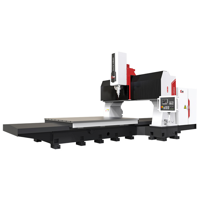
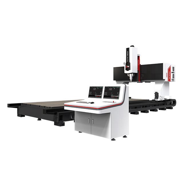
Our friction stir welding equipment is designed to meet these requirements, enabling improved process stability, repeatability, and weld consistency in demanding copper and copper-alloy applications. Explore our friction stir welding machines for copper and high-conductivity materials to find the right solution for your application
Friction stir welding copper offers a reliable solution for producing high-integrity joints in demanding electrical and thermal applications. However, success depends on precise control of heat input, tool design, and process parameters. As copper continues to play a critical role in modern industries, optimized FSW processes will become increasingly important.
For manufacturers working with copper bus bars, heat exchangers, connectors, or other high-conductivity components, achieving stable weld quality requires more than theoretical parameter optimization.
It requires a friction stir welding system with stable control, proper tooling support, and application-matched configuration.
If you are facing:
Tunnel defects
Tool wear
Unstable material flow
Inconsistent weld quality
A: Friction stir welding copper faces challenges like managing copper’s high thermal conductivity, controlling intermetallic compounds, avoiding defects such as voids and cracks, and handling residual stresses. Optimizing friction stir welding copper parameters and tool selection is crucial to overcome these issues and achieve high joint quality.
A: Selecting tools with high wear resistance, thermal stability, and chemical compatibility—such as WC-Co or nickel alloys—is essential for friction stir welding copper. Proper tool geometry ensures effective material flow and minimizes defects, directly influencing weld quality and tool lifespan.
A: Best practices include thorough surface preparation, using wear-resistant tools with optimized geometry, carefully controlling rotational speed, welding speed, tilt angle, and plunge depth, and employing real-time monitoring of temperature and forces to ensure defect-free friction stir welding copper joints.
A: Optimizing rotational speed, welding speed, tool tilt angle, and plunge depth balances heat input and material flow. Cooling techniques like liquid nitrogen sprays help refine microstructure. These adjustments reduce friction stir welding copper defects and improve joint mechanical properties.
A: Friction stir welding copper produces joints with refined grain structure, superior mechanical properties, and minimal distortion. It consumes less energy, avoids fusion-related defects, and reduces environmental impact compared to fusion welding techniques for copper alloys.
Yes, but it requires precise control of heat input, tool design, and process parameters.
Because copper has much higher thermal conductivity, which removes heat quickly from the weld zone.
Tungsten carbide and nickel-based alloys are commonly used due to their wear resistance and thermal stability.
Properly controlled FSW can maintain good electrical conductivity with minimal degradation.
Tunnel defects, voids, flash formation, and tool wear are typical issues.
In thick sections or high-conductivity alloys, preheating can improve weld quality.
Electrical systems, heat exchangers, battery components, and power equipment.
Yes, but intermetallic compounds must be controlled to avoid brittle joints.