Views: 0 Author: Site Editor Publish Time: 2026-07-15 Origin: Site
Joining 6061 aluminum alloy presents tough metallurgical hurdles on the factory floor. Traditional fusion welding exposes the material to hot cracking, extensive porosity, and severe mechanical degradation in the Heat-Affected Zone (HAZ). These defects ruin structural integrity and drive up scrap rates. Manufacturing engineers need a reliable way to achieve high-strength, low-distortion joints in 6061 assemblies. You must hold strict production tolerances, cut post-weld rework, and eliminate manufacturing waste.
Friction Stir Welding (FSW) provides a solid-state alternative that bypasses the liquid phase entirely. This guide breaks down the technical feasibility, process parameters, mechanical outcomes, and implementation realities of Friction Stir Welding Aluminum 6061. We will evaluate the exact steps needed to support your equipment and process adoption decisions, ensuring you can deploy this technology effectively in your fabrication facility.
Solid-State Superiority: FSW eliminates solidification defects (porosity, hot cracking) in 6061 aluminum by joining the material below its melting point, preserving up to 80-90% of the base metal's tensile strength.
Parameter Dependency: Joint quality relies strictly on the precise control of tool rotational speed, traverse speed, and axial downward force to achieve optimal thermomechanical deformation and hot shear flow.
Tooling and Fixturing Rigidity: Successful implementation requires highly rigid clamping systems and specialized tool geometries of superior hardness to withstand the high mechanical forces generated during the plunge and traverse phases.
Table of Contents
Traditional fusion welding methods severely compromise the structural integrity of 6061-T6 aluminum. The intense heat required to melt the base metal destroys the T6 temper. This leads to a drastic reduction in tensile and yield strength across the weld zone. You often have to over-design components just to compensate for these weakened joints. Fusion processes also force you to use filler metals like 4043 or 5356 alloys. Introducing these dissimilar metals creates galvanic and chemical mismatches that complicate post-weld finishing and increase localized corrosion risks.
High heat input and rapid cooling cycles inherent in MIG and TIG welding induce massive distortion and residual stress within the assembly. Managing this distortion requires extensive clamping, pre-heating, and post-weld straightening procedures. These steps add heavy labor hours to the manufacturing cycle. The probability of solidification cracking and porosity remains high, forcing you to rely on rigorous non-destructive testing and rework to ensure joint reliability.
Process Characteristic | MIG/TIG Fusion Welding | Friction Stir Welding (FSW) |
|---|---|---|
State of Material | Liquid (Melting occurs) | Solid-State (No melting) |
Filler Material | Required (4043, 5356) | None (Autogenous) |
Shielding Gas | Required (Argon/Helium) | None required |
Joint Strength Retention | 40% - 60% of base metal | 80% - 90% of base metal |
Distortion Levels | High (Requires straightening) | Very Low |
Friction Stir Welding operates as an autogenous, non-melting process. It circumvents the primary issues associated with fusion welding. A non-consumable rotating tool plunges into the joint line. It generates frictional heat that softens the aluminum without melting it. The tool's mechanical action forces the plasticized material to undergo dynamic recrystallization. This forges a dense, fine-grained microstructure. The material remains below its solidus temperature throughout the entire cycle.
The success criteria for adopting Friction Stir Welding Aluminum include achieving zero solidification cracking, minimal thermal distortion, and exceptionally high joint efficiency. The process does not require consumable filler materials or shielding gases. It simplifies your supply chain and reduces environmental impact on the shop floor. The resulting joints exhibit superior mechanical properties compared to fusion welds. This makes FSW a highly attractive solution for critical structural applications.
The T6 temper behavior of 6061 aluminum changes during friction stir welding because the thermal cycle modifies the Mg-Si strengthening precipitates. In the Stir Zone, intense deformation and elevated temperatures can partially dissolve the precipitates, while the Heat-Affected Zone typically experiences over-aging and precipitate coarsening. As a result, the lowest hardness and strength usually occur in the HAZ rather than in the weld nugget. Compared with MIG or TIG welding, however, FSW limits peak temperature and preserves a much larger portion of the original T6 mechanical performance.
The ability of FSW to produce high-strength, lightweight joints makes it invaluable across multiple high-performance industries. Reducing vehicle weight directly translates to improved fuel efficiency and increased payload capacity. FSW enables the fabrication of complex, lightweight aluminum structures that maintain the necessary structural integrity to withstand dynamic operational loads.
Rail Rolling Stock: FSW joins large extruded passenger car panels, ensuring a smooth, continuous surface with minimal distortion.
Automotive EV Components: Manufacturers use the process for EV battery trays and chassis components, where leak-tight, high-strength joints are critical for safety.
Aerospace Structures: FSW replaces traditional riveting in fuselage structures to reduce weight and eliminate stress concentrations.
Marine Applications: Shipbuilders rely on FSW for large deck panels, providing excellent corrosion resistance and structural stability in saltwater environments.
Typical applications of Friction Stir Welding Aluminum 6061 include EV battery trays, lightweight vehicle frames, motor and inverter housings, railway car body panels, aerospace structural panels, marine deck assemblies, heat sinks, and large aluminum extrusions. These components benefit from the low distortion, high fatigue resistance, and strong joint efficiency of FSW, especially when dimensional accuracy and leak-tight performance are critical.
Proper surface preparation dictates the success of FSW joints in 6061-T6 aluminum. The natural oxide layer that forms on aluminum surfaces possesses a melting point significantly higher than the base metal. If you do not manage it, this oxide layer gets trapped within the weld nugget. It forms a continuous line of weakness known as a kissing bond. Surface contaminants like machining lubricants, moisture, and dirt introduce hydrogen porosity and degrade the mechanical properties of the joint.
You must remove the oxide layer and all contaminants immediately prior to welding. Effective methods include mechanical degreasing followed by aggressive wire brushing or chemical etching. Maintaining strict tolerance requirements for joint fit-up is equally important. Excessive gaps or surface mismatch between the mating plates lead to insufficient material flow. This results in void formation and incomplete consolidation of the plasticized aluminum.
FSW accommodates various joint configurations, provided your tooling and fixturing can support the applied forces. Butt joints are the most common and straightforward application. They offer excellent mechanical properties and a flush surface finish. Lap joints work well for joining overlapping sheets, but they require careful control of the tool plunge depth. You must ensure adequate mixing across the interface without excessively thinning the top sheet. T-joints and Corner joints are feasible but demand specialized tooling and complex fixturing to counteract the multi-directional forces generated during the process.
Friction Stir Spot Welding (FSSW) serves as a highly effective solid-state alternative to traditional rivets and resistance spot welding. It excels in thin sheet applications. FSSW eliminates the need for consumable fasteners and avoids the metallurgical degradation associated with resistance welding. The process creates a strong, localized bond through the same thermomechanical mechanisms as continuous FSW.
A stable weld parameter window defines the range of rotational speed, traverse speed, axial force, plunge depth, and tool tilt that produces defect-free joints with acceptable strength. The lower boundary of the window is limited by insufficient heat generation, which can cause tunneling, lack of penetration, and tool overload. The upper boundary is limited by excessive heat input, which leads to flash formation, HAZ softening, grain coarsening, and reduced strength retention. Parameter trials should therefore identify not only a single optimum setting, but also a repeatable operating range that accommodates normal variations in plate thickness, tool wear, and ambient temperature.
The interplay between tool rotational speed and traverse speed dictates the heat generation and cooling rate during the FSW process. Rotational speed controls the frictional heat input. It softens the material to facilitate plastic flow. Traverse speed determines the rate at which the tool moves along the joint line. This influences productivity and the thermal cycle experienced by the base metal. You must balance these two parameters to achieve optimal thermomechanical deformation.
The pitch ratio, defined as the feed-to-speed ratio, provides a useful metric for establishing baseline parameters for 6061 aluminum. Deviations from the optimal pitch ratio lead to distinct defect categories. Cold defects occur when you generate insufficient heat. This happens with high traverse speeds or low RPM, resulting in lack of penetration, internal voids, or tool breakage. Hot defects arise from excessive heat input. They cause localized melting, excessive flash formation, and severe degradation of the HAZ.
Material Thickness (6061-T6) | Rotational Speed (RPM) | Traverse Speed (mm/min) | Axial Force (kN) |
|---|---|---|---|
3 mm | 1000 - 1200 | 300 - 400 | 4 - 6 |
6 mm | 800 - 1000 | 200 - 300 | 8 - 12 |
10 mm | 600 - 800 | 100 - 200 | 15 - 20 |
Maintaining a consistent axial downward force ensures proper forging of the plasticized aluminum. This force compresses the material beneath the tool shoulder. It prevents the escape of plasticized metal and ensures complete consolidation of the weld nugget. Insufficient axial force leads to surface defects and incomplete root penetration. Excessive force causes excessive thinning of the joint and premature tool wear.
The tool tilt angle plays a vital role in the process mechanics. You typically set it between 1 and 3 degrees trailing the direction of travel. The tilt helps compress and contain the plasticized material behind the tool. It facilitates a smooth surface finish and prevents surface tearing. Precise control of the plunge depth is equally critical. The pin must penetrate deeply enough to ensure full joint integration without contacting the backing plate. Hitting the anvil damages the tool and contaminates the weld.
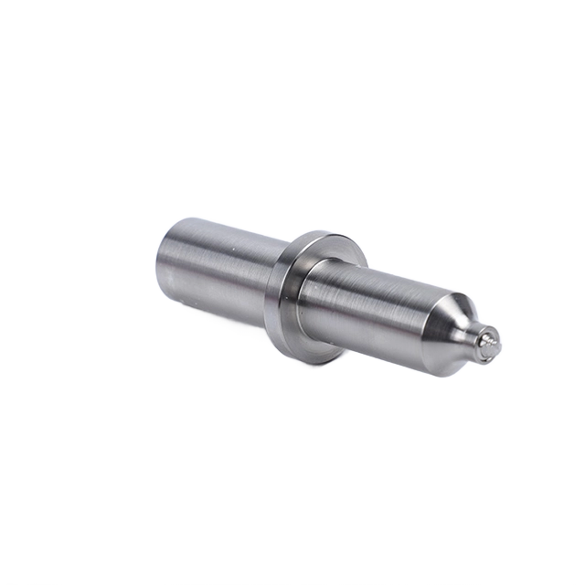
The hot shear plastic deformation mechanism relies heavily on the specific geometry of the FSW tool. The pin profile dictates the material mixing dynamics and vertical flow within the stir zone. You can use threaded, fluted, or tapered pins. Effective pin designs ensure thorough disruption of the oxide layer and homogeneous blending of the mating surfaces. The shoulder design generates the majority of the frictional heat and contains the plasticized material within the joint.
Tool material selection for welding 6061 aluminum depends on production volume and operational demands. H13 tool steel works well for standard applications due to its excellent toughness and thermal fatigue resistance. For high-volume production runs, you need ultra-hard materials like Tungsten Carbide or Cobalt-based alloys. These advanced materials maintain their geometric integrity over longer production runs. They ensure consistent weld quality and reduce machine downtime for tool changes.
The FSW process creates three distinct microstructural zones within the joint. The Stir Zone experiences intense plastic deformation and high temperatures. This results in dynamic recrystallization. The process generates a fine, equiaxed grain structure that significantly enhances the mechanical properties of the nugget. Adjacent to the nugget is the Thermo-Mechanically Affected Zone (TMAZ). It undergoes both thermal cycling and plastic strain but does not recrystallize. The Heat-Affected Zone (HAZ) experiences only thermal cycling. This leads to precipitate coarsening and over-aging in 6061-T6.
The fine, equiaxed grain structure in the nugget zone contributes to superior tensile strength and ductility compared to the as-cast structure of fusion welds. This refined microstructure improves the joint's resistance to fatigue crack initiation and propagation. You must understand the characteristics of these distinct zones to predict the overall mechanical performance of the welded assembly.
Empirical data demonstrates that 6061 FSW joints consistently achieve high ultimate tensile strength and yield strength compared to the base metal. Joint efficiencies of 80% to 90% are routinely attainable. This far exceeds the capabilities of traditional fusion welding on the same alloy. When tensile failures do occur, they typically manifest in the HAZ. The thermal cycle causes precipitate coarsening and over-aging there, creating a localized region of reduced strength.
Under a properly controlled weld parameter window, strength retention after FSW for 6061-T6 typically reaches approximately 80% to 90% of the base metal tensile strength. The Stir Zone often retains relatively high strength because of grain refinement, while the primary reduction occurs in the softened HAZ. Actual retention depends on plate thickness, heat input, traverse speed, cooling rate, and whether post-weld aging is applied.
The fatigue life of FSW joints is markedly superior to that of fusion joints. This improvement comes from the absence of stress-concentrating weld toes, internal porosity, and solidification cracks. The smooth surface profile and dense, defect-free internal structure of an optimized FSW joint provide excellent resistance to cyclic loading. This makes the process highly suitable for dynamically loaded structures in aerospace and automotive applications.
FSW enables the joining of 6061 aluminum to dissimilar materials. This task is notoriously difficult with fusion welding due to the formation of brittle intermetallic compounds (IMCs). Joining 6061 to AISI 1018 carbon steel, stainless steel, or pure copper is feasible using specialized FSW techniques. The solid-state nature of the process limits the diffusion kinetics. It restricts the growth of IMC layers at the interface.
Control strategies for managing IMC layer thickness involve precise tool offset techniques and strict temperature regulation. You offset the tool slightly into the softer aluminum side. The tool pin avoids direct, aggressive engagement with the harder material. This approach generates sufficient heat to plasticize the aluminum while minimizing the mechanical disruption and thermal exposure of the dissimilar metal. It results in a strong, reliable bond with a controlled IMC layer.
Compared with 7075 aluminum, 6061 generally offers a wider weld parameter window, lower flow stress, and reduced tool loading, making it easier to weld consistently in high-volume production. However, 7075 provides higher base-metal strength and requires stricter heat-input control to limit HAZ degradation. Compared with ADC12 die-cast aluminum, 6061 contains far less entrapped gas and casting porosity, so it presents a lower risk of blistering, groove-like voids, and unstable material flow during FSW. ADC12 typically requires lower heat input, tighter surface preparation, and more aggressive quality inspection.
To recover the mechanical properties lost in the HAZ during welding, you can apply post-weld artificial aging. This thermal cycle involves solution heat treating the entire assembly followed by artificial aging to re-precipitate the strengthening phases. While effective at restoring near base-metal strength, PWHT requires large furnaces. It can induce thermal distortion if you do not manage it carefully.
Post-weld finishing of autogenous FSW joints offers significant advantages over fusion welds. FSW does not use dissimilar filler alloys. The weld zone exhibits excellent anodizing behavior. The anodized finish remains uniform in color and texture across the joint. It eliminates the aesthetic mismatches commonly associated with TIG or MIG welds. This uniform appearance is highly desirable for consumer-facing products and architectural applications.
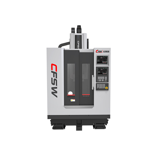
Implementing FSW requires careful consideration of the equipment platform. Purpose-built FSW gantries offer superior stiffness, high axial force capabilities, and robust duty cycles. Manufacturers design them specifically for the rigorous demands of the process. These dedicated machines provide the highest level of process control and repeatability for heavy industrial applications.
Retrofitting heavy-duty CNC milling machines offers an entry point for facilities with existing equipment. However, standard CNC machines often lack the necessary structural rigidity and spindle bearings to withstand sustained high axial loads. You must evaluate the necessity of real-time force-control systems versus position-control systems. Force-control systems dynamically adjust the plunge depth to maintain consistent forging pressure. This is essential for welding complex profiles or managing variations in material thickness.
The extreme lateral, longitudinal, and axial forces generated during friction stir welding necessitate highly robust fixturing and clamping systems. The tooling must rigidly secure the workpieces. It prevents any movement or separation along the joint line during the plunge and traverse phases. Inadequate clamping leads to joint separation, excessive flash, and severe weld defects.
Engineering requirements for fixturing include the use of substantial backing plates to support the axial load and prevent root blowout. You need rigid top-clamping to secure the plates firmly against the anvil. This prevents plate lifting and ensures consistent contact with the tool shoulder. Custom fixturing is often necessary for complex geometries. It ensures high-quality, repeatable results in production.
Tunneling, or wormhole defects, occur as continuous sub-surface voids running along the length of the weld. The root cause is typically insufficient material flow into the cavity created behind the advancing pin. This lack of consolidation is often driven by excessively high traverse speeds or low rotational speeds. The tool fails to generate adequate heat and plasticization.
Mitigating tunneling defects requires careful parameter adjustments. Increasing the rotational speed or decreasing the traverse speed enhances heat generation and improves material flow. Ensuring proper tool plunge depth and maintaining consistent axial force helps force the plasticized material into the cavity. This eliminates the sub-surface voids and ensures a fully consolidated joint.
Kissing bonds represent a critical defect where the mating surfaces are in intimate contact but lack true metallurgical bonding. This occurs when the natural oxide layer is not sufficiently disrupted and dispersed during the stirring action. Joint line remnants trace the path of the undisrupted oxide layer through the weld nugget. They create a significant stress riser.
Mitigation strategies focus on thorough chemical or mechanical oxide removal immediately prior to welding. Optimizing the pin length to ensure full penetration and adequate disruption of the root interface is critical. Adjusting the plunge depth and utilizing tool geometries designed to enhance vertical material flow help break up and disperse the oxide layer. This prevents the formation of kissing bonds.
Excessive flash formation occurs when plasticized material is extruded out from under the tool shoulder rather than being contained within the joint. This defect is typically caused by excessive heat input, improper shoulder plunge depth, or significant tool wear. Surface galling presents as a rough, torn surface finish. It often results from incorrect tool tilt or insufficient axial force.
The impact of severe flash includes localized material thinning across the joint and increased post-weld machining requirements to restore a flush surface. Controlling heat input through optimized RPM and traverse speeds is essential. Ensuring correct tool tilt and maintaining precise plunge depth control minimizes flash and achieves a smooth, defect-free surface finish.
Adopting FSW requires acknowledging the initial setup associated with specialized equipment and custom fixturing. Purpose-built FSW machines and the rigid clamping systems required represent a substantial commitment compared to traditional fusion welding setups. You must evaluate this against the projected production volumes and the specific performance requirements of the application.
The operational efficiency for FSW is significantly higher than fusion welding. The process eliminates the need for consumables such as shielding gases and filler wires. Energy consumption is generally lower. The high repeatability of the automated process reduces scrap rates and costly rework. FSW often requires lower operator certification requirements compared to manual TIG or MIG welding. This contributes to long-term production efficiency and streamlined factory operations.
To successfully implement FSW for 6061 aluminum in your facility, follow these actionable next steps:
Audit your current joint designs to identify candidates for solid-state welding.
Upgrade your fixturing to handle the high axial and lateral forces of the FSW process.
Run parameter trials to establish the optimal pitch ratio for your specific material thickness.
Implement aggressive pre-weld cleaning protocols to eliminate oxide layers and surface contaminants.
A: Traditional fusion welding destroys the T6 temper in the HAZ. FSW minimizes this degradation by operating in the solid state. You retain 80 to 90 percent of the base metal strength, though some over-aging still occurs in the HAZ.
A: No, FSW is a solid-state process that does not melt the aluminum. Therefore, it does not require shielding gases or consumable filler wires to protect the weld pool from atmospheric contamination.
A: Tool life depends on the tool material and processing parameters. Standard H13 tool steel can weld hundreds of meters of 6061 aluminum. Advanced materials like Tungsten Carbide offer significantly longer lifespans in high-volume production.
A: Yes, FSW can join 6061 aluminum to dissimilar metals like steel. This requires precise tool offset techniques and temperature control to manage the formation of brittle intermetallic compound layers at the interface.
A: Tunneling defects are prevented by ensuring adequate heat generation and material flow. You achieve this by optimizing the pitch ratio, increasing RPM or decreasing traverse speed, and maintaining sufficient axial downward force.
A: FSW generally produces a smooth surface finish. Post-weld machining is only required if excessive flash is generated due to improper parameters or if a perfectly flush surface is mandated by the design specifications.