Views: 0 Author: Site Editor Publish Time: 2026-11-19 Origin: Site
Table of Contents
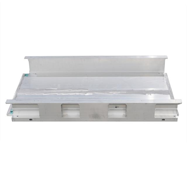
Cooling Plate Fixture and Backing Design plays a critical role in friction stir welding (FSW) of thin aluminum cooling plates. Proper fixture and backing plate structures provide stable clamping, accurate joint positioning, and reliable support throughout the welding process, helping prevent channel deformation and welding distortion.
Key design considerations include fixture rigidity, clamping force, backing plate support, and tool clearance. These factors directly affect weld quality, plate flatness, and production consistency in aluminum liquid cooling plate manufacturing.
Fixture rigidity plays a vital role in friction stir welding (FSW) of thin aluminum cooling plates. The fixture must resist the downward and lateral forces applied by the rotating tool without deflecting or shifting. Any movement changes the relative position between the tool and workpiece, leading to inconsistent penetration and potential weld defects like incomplete root consolidation or flash.
A rigid fixture creates a stable platform that maintains joint alignment throughout the welding cycle. It also reduces vibration and helps keep the weld path consistent. Since cooling plates have thin walls and delicate channel structures, the fixture must be designed to support the plate firmly without causing distortion. The rigidity should extend from the clamping points through the backing plate to the machine table, forming a continuous load path that prevents any local bending under the axial tool load.
Clamping thin aluminum cooling plates requires a careful balance. The clamps must hold the plate firmly near the weld path to prevent lifting or sliding during welding, but excessive force risks deforming the thin material or crushing the channel walls.
Key clamping strategies include:
Position clamps as close as possible to the weld line while ensuring tool clearance.
Use multiple clamps distributed along long weld seams to prevent local movement.
Employ soft or compliant contact pads to protect the aluminum surface from clamp marks.
Adjust clamping force based on plate thickness, joint design, and fixture rigidity.
Coordinate clamp placement with locating features to avoid over-constraining the part.
Proper clamping prevents joint separation and maintains consistent tool penetration, which is critical for leak-tight welds in cooling plates.
Backing support directly beneath the weld is essential to prevent channel wall collapse under the axial force of the FSW tool. Without firm support, the thin land between the channel and cover can buckle or deform, causing voids or leaks in the weld seam.
Backing plates or inserts must:
Provide continuous, flat support along the entire weld path.
Match the contour of the cooling plate to avoid gaps or uneven contact.
Have sufficient stiffness to resist deflection under welding loads.
Be made of materials that withstand wear and thermal cycling.
Allow easy replacement or maintenance to ensure consistent support over production runs.
An unsupported or poorly supported channel can lead to root flaws and compromised sealing integrity.
Maintaining precise joint alignment is crucial. The fixture must prevent any lateral or vertical movement of the cooling plate parts during welding. Even slight shifts can misalign the joint, causing weld defects or leaks.
This requires:
Accurate locating features such as pins or stops to position the plate reproducibly.
Clamps that hold the plate securely without causing distortion.
A backing plate that supports the plate evenly to minimize bending.
A fixture design that distributes forces evenly and avoids stress concentrations.
Together, these elements ensure the tool follows the intended weld path exactly, producing consistent, high-quality welds.
Thermal expansion during FSW can cause dimensional changes and distortion in thin aluminum cooling plates. The fixture must accommodate this expansion without losing joint alignment or causing stress.
Effective thermal management includes:
Designing locators and clamps to allow controlled movement in expansion directions.
Avoiding over-constraining the plate, which can cause warping or buckling.
Selecting backing materials with compatible thermal expansion coefficients.
Considering thermal conductivity of the fixture to help dissipate heat.
Allowing slight clearance or floating support where appropriate.
Balancing fixture rigidity with controlled thermal movement helps maintain flatness and prevents distortion that could impair cooling plate performance.
Tip: Position clamps close to the weld line and distribute them evenly along long seams to prevent local lifting or movement during FSW of thin aluminum cooling plates.
The backing plate plays a crucial role in friction stir welding (FSW) of thin aluminum cooling plates. It supports the workpiece directly beneath the weld area, resisting the downward force from the welding tool. This support prevents the thin lands between channels from collapsing or deforming, which could cause leaks or weak welds. The backing plate also helps maintain consistent tool penetration and joint alignment, ensuring the weld quality remains high across the entire seam. Without firm backing, the aluminum cover can deflect under the tool, leading to incomplete root consolidation or excessive flash.
Choosing the right backing plate material is vital. It must combine high stiffness and wear resistance to withstand repeated welding cycles. Materials like hardened steel or tool steel are common due to their durability and strength. Thermal behavior matters too. The thermal expansion behavior of the backing plate should be considered alongside its stiffness and thermal conductivity. Differences in thermal expansion between the backing plate and aluminum workpiece may affect contact conditions and dimensional stability during welding, depending on the fixture design and operating conditions. Additionally, good thermal conductivity helps dissipate heat from the weld zone, aiding in controlling thermal distortion.
Continuous and uniform contact between the backing plate and the cooling plate is essential. The backing surface should be machined flat and clean to avoid gaps beneath the weld path. Even small voids can lead to localized deflection during welding. For complex weld paths or curved channels, the backing plate may need to be contoured or segmented to match the part geometry precisely. This ensures the entire weld length receives stable support, preventing channel collapse or bending. Consistent backing also helps maintain the correct tool-to-workpiece distance, which is critical for leak-free welds.
Backing plates endure significant wear and thermal cycling. Designing them for easy maintenance and replacement reduces downtime and keeps production efficient. Modular backing inserts or replaceable wear pads allow quick swaps without removing the entire fixture. Clear indexing features help reinstall backing components in the exact position, preserving weld consistency. Accessibility for cleaning and inspection is also important to prevent buildup of aluminum debris or contamination that could affect support quality.
Backing plate stiffness directly impacts weld quality. A stiff backing plate prevents elastic deflection under the axial force of the FSW tool. If the backing plate flexes, the workpiece may lift or bend, causing inconsistent tool penetration and weld defects such as root flaws or flash. Stiffness depends on material choice, thickness, and support from the fixture base. For thin aluminum cooling plates, backing plates must be thick enough or reinforced to maintain rigidity along long weld seams. Supporting the backing plate itself on a rigid fixture frame and machine table completes the load path, ensuring the entire system resists deformation during welding.
Clamps must be placed as near as possible to the weld line to prevent local lifting or sliding during friction stir welding (FSW). When clamps sit far away, the thin aluminum cooling plate may flex or separate near the joint, even if the overall clamping force is high. Positioning clamps close to the weld path ensures the joint remains tight, helping maintain consistent tool penetration and preventing leaks. However, clamps must not interfere with the rotating tool or spindle, so clearance is crucial.
Applying enough clamping force to keep the plate stable is vital, but too much force risks deforming the thin aluminum or crushing delicate channel walls. The clamping system should distribute force evenly and use compliant contact pads or soft materials to protect the surface. The right balance depends on plate thickness, joint design, fixture rigidity, and backing support. Over-clamping can cause distortion, while under-clamping allows movement, both leading to weld defects.
For extended weld seams, relying on just a few clamps can allow sections of the plate to lift or shift between clamps. Using multiple clamps spaced evenly along the weld path provides consistent restraint and prevents local deformation. The spacing depends on factors like material stiffness, weld length, and backing plate support. Distributed clamping also reduces the risk of thermal distortion by spreading forces over a larger area.
The fixture design must ensure that clamps and other components remain clear of the full FSW tool envelope. This includes the rotating pin, shoulder, tool holder, and spindle assembly throughout the entire welding cycle—from tool approach and plunge to travel and retraction. Interference can cause tool damage, poor weld quality, or machine stoppage. Clearance checks should cover weld start and end positions and any changes in tool orientation for complex paths.
Cooling plates often require welds along curved or multi-directional paths. Fixtures must accommodate these by allowing clamps and backing supports to follow the contour without blocking tool movement. Special attention is needed at weld start and exit points to ensure the tool can enter and leave smoothly without collision. For exit strategies involving retractable pins, the fixture must provide clearance for pin withdrawal and material reconsolidation to avoid exit hole defects.
Tip: Place clamps close to the weld path and space them evenly along long seams to prevent local movement during FSW, while always verifying full tool and spindle clearance for safe, consistent welding.
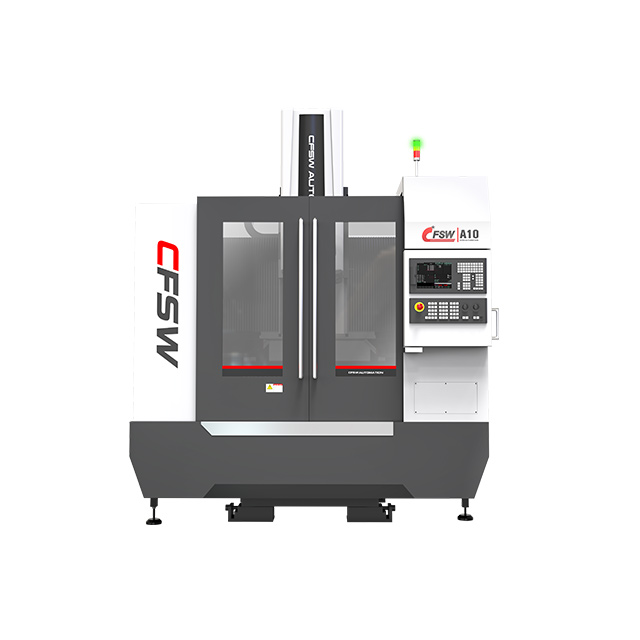
For friction stir welding (FSW) of thin aluminum cooling plates, machine rigidity is crucial. The machine must be stiffer than the workpiece to maintain precise tool positioning. The Z-axis, which controls vertical movement, must hold depth repeatably under welding forces. Any Z-axis movement or deflection can cause inconsistent penetration, risking leaks or root flaws.
Thin plates are especially sensitive because small deflections can cause the tool pin to break into the channel or fail to consolidate the root properly. A rigid machine frame combined with a stiff spindle and Z-axis actuator ensures stable axial force control and repeatable weld depth.
Cooling plate welding often involves many short weld passes due to channel layouts. Dual-worktable machines improve productivity by allowing one fixture to weld while the operator loads or unloads the other. This setup reduces idle time because welding cycles can be shorter than handling times.
A dual-worktable system also supports consistent fixture clamping and positioning, reducing setup errors. It is especially beneficial for high-volume production of cooling plates where cycle time and repeatability are critical.
Effective FSW requires monitoring welding forces to maintain quality. Machines equipped with force sensors can log axial force, torque, and position data during welding. This data helps verify that each weld stays within the process window, avoiding defects caused by tool wear or material variation.
Data logging also supports traceability, showing exactly how each plate was welded. It enables quick identification of process drifts and supports continuous improvement efforts.
The fixture and backing plate must work in harmony with the machine's rigidity and control systems. A stiff backing plate reduces deflection under axial load, complementing machine rigidity. The fixture's ability to maintain flatness and joint alignment allows the machine to apply force accurately.
If the fixture or backing plate flexes, the machine may compensate with excessive force or depth, causing defects. Therefore, fixture design should consider machine stiffness and force capabilities to optimize the entire system.
Tool selection directly influences weld quality and machine requirements. For thin aluminum covers, pin length and shoulder diameter should be matched to the plate thickness and joint design to achieve proper material flow, penetration, and heat input while limiting excessive flash. Stationary shoulder tools can further lower surface defects by controlling heat.
The tooling must match machine spindle speed and torque limits to avoid overheating or premature wear. Tool exit strategies, such as retractable pins, require machine and fixture coordination for smooth tool withdrawal without causing exit holes.
Tip: Ensure your FSW machine offers high Z-axis stiffness and integrates force data logging to maintain consistent weld depth and quality when joining thin aluminum cooling plates.
Designing fixtures and backing plates for thin aluminum cooling plates in friction stir welding (FSW) presents unique challenges. These challenges can impact weld quality, part integrity, and production efficiency. Understanding common issues and applying targeted solutions helps create reliable, leak-free cooling plates.
Thin aluminum cooling plates have delicate channel walls that risk collapsing under the axial force from the FSW tool. Without proper backing support, the narrow land between the channel and cover can buckle or deform, causing voids or leaks.
Solution:
Use a backing plate with high stiffness and continuous support along the weld path.
Match backing plate contours closely to the cooling plate geometry to avoid gaps.
Employ replaceable backing inserts in critical areas to maintain consistent support.
Design the fixture to transfer axial loads efficiently from the tool through the backing plate to the machine table.
Incomplete root consolidation happens when the weld does not fully penetrate the joint at the root, leaving gaps that cause leaks. Excessive flash, on the other hand, results from too much heat or material displacement, creating surface defects and scrap.
Solution:
Maintain precise joint alignment using accurate locating features and stable clamping near the weld.
Control axial force and tool penetration depth carefully with a rigid fixture and backing plate.
Use force data logging during welding to verify consistent process parameters.
Select tooling optimized for thin aluminum covers, such as tools with shorter pins or stationary shoulders.
Thermal expansion during welding can cause distortion, warping, or bowing of thin cooling plates. Distortion reduces thermal contact with heat sources and may create stress points.
Solution:
Allow controlled thermal movement using floating locators or compliant clamps.
Avoid over-constraining the part, which can increase distortion.
Use backing materials with compatible thermal expansion coefficients.
Distribute clamping force evenly along the weld seam to reduce localized stress.
Validate fixture design through trial welding and measure post-weld flatness.
Fixture deflection or insufficient clamping allows part movement during welding. This can cause joint misalignment, incomplete root consolidation, or other weld defects.
Solution:
Design fixtures with high rigidity from clamps through backing plates to the machine table.
Position clamps close to the weld path to prevent local lifting or sliding.
Distribute clamps evenly along long welds for consistent restraint.
Use compliant clamp pads to protect thin aluminum surfaces without sacrificing holding force.
Check for fixture wear or loose fasteners regularly and maintain clamping components.
Exit holes form when the welding tool retracts, leaving a keyhole that can become a leak path. This is especially critical on cooling plates where the weld seam forms a hydraulic seal.
Solution:
Design exit strategies such as run-off tabs or dual-side access to move the exit hole away from sealed areas.
Use retractable pin tools that withdraw the pin gradually and reconsolidate the material to close the hole.
Ensure backing plate support extends through the weld end region to prevent local collapse.
Program controlled tool retraction speeds and axial forces to minimize exit defects.
Ensuring the quality of friction stir welded (FSW) thin aluminum cooling plates requires a thorough inspection, leak testing, and validation process. These steps confirm the fixture’s ability to hold parts securely and produce leak-tight, flat welds consistently.
Inspection should happen in layers, each adding confidence to weld integrity:
Visual Inspection: Check weld surface for uniformity, absence of cracks, excessive flash, or discoloration. Surface appearance can provide an initial indication of weld consistency, but it should be evaluated alongside process data and other inspection results.
Dimensional Inspection: Measure plate flatness, weld seam width, and critical dimensions. This confirms the fixture holds parts without distortion.
Cross-Sectional Analysis: Periodically section sample welds to examine root penetration, consolidation, and internal defects like voids or tunnels. This destructive test validates the weld’s internal quality.
Process Data Review: Analyze recorded force, torque, and position data logged during welding for consistency and process stability.
Both testing types are essential for different purposes:
Destructive Testing: Includes metallographic sectioning, tensile testing, and bend tests. It reveals internal flaws and mechanical properties but sacrifices the part.
Non-Destructive Testing (NDT): Non-destructive testing methods such as ultrasonic testing, radiographic testing, and dye penetrant inspection can be used to assess weld quality. Their ability to detect specific defects depends on the inspection method, defect characteristics, material, and testing procedure. NDT is vital for production inspection.
Leak testing is the ultimate functional check for cooling plates:
Pressure Decay Testing: The plate is pressurized with air or gas, and pressure loss over time is monitored. It’s simple but less sensitive.
Helium Leak Testing: Uses helium’s small molecular size to detect tiny leaks. It’s more sensitive and preferred for critical applications.
Bubble Testing: Submerging the plate in water and looking for bubbles during pressurization. Useful for quick checks but less precise.
Leak tests should replicate service conditions, including pressure range and hold times, to ensure real-world reliability.
Maintaining detailed records links each cooling plate to:
Welding parameters (force, speed, position)
Tool serial numbers and condition
Fixture version and setup details
This traceability enables root cause analysis if defects arise and supports continuous process improvement.
Before production, trial welding confirms fixture effectiveness:
Load parts and verify alignment and clamping.
Weld sample plates under production parameters.
Inspect weld quality, flatness, and dimensional stability.
Perform leak tests on samples.
Monitor fixture and backing plate condition for wear or deformation.
Adjust fixture design or clamping if issues occur.
Multiple trial runs ensure repeatability and robustness before full-scale manufacturing.
Moving from prototype to production means proving the fixture can handle repeated welding cycles without losing performance. It’s critical to confirm how many welds a single tool can perform before penetration depth or weld quality shifts. Tool wear impacts the process window, so knowing the tool life helps plan maintenance or replacement intervals.
Production fixtures must also withstand continuous loading without loosening or deforming. Regular cleaning schedules prevent aluminum buildup that could reduce backing plate contact or cause clamping issues. Trial runs on representative batches reveal if the fixture maintains stable joint alignment and backing support over time.
Manufacturers often produce several cooling plate models sharing similar channel layouts but different dimensions or features. Designing fixtures flexible enough to accommodate these variants reduces tooling costs and changeover time.
Modular backing plates with interchangeable inserts can match different weld paths or channel contours. Adjustable clamps and locating features allow quick reconfiguration while preserving rigidity and repeatability. Dual-worktable machines help handle variant changeovers by staging different fixtures side by side.
However, any change in fixture geometry should be validated to ensure consistent support and clamping force. Even small differences in backing contact or clamp position can affect weld quality and leak tightness.
Automating fixture loading and unloading improves throughput and reduces operator variability. Dual-worktable machines paired with robotic handlers enable continuous welding cycles by preparing one fixture while welding another.
Automated clamping systems with pneumatic or hydraulic actuators provide consistent force and reduce setup time. Sensors integrated into fixtures can verify clamp engagement and part presence, preventing errors before welding.
Data logging combined with automated handling supports traceability and quality control. It also allows quick parameter recall for different part numbers, improving flexibility in high-mix production environments.
Material variability between lots can slightly change weld behavior. Production fixtures must accommodate these differences without compromising joint integrity.
Consistent backing support and clamping prevent process drift caused by material springback or thickness variation. Monitoring force and torque data during welding helps detect subtle changes early.
Periodic validation with sample parts from new material lots ensures the fixture and process remain within specification. This avoids surprises that could cause leaks or rework downstream.
After welding, cooling plates often require machining to meet flatness or dimensional tolerances. Fixture design should consider how post-weld distortion affects these steps.
Controlling distortion during welding reduces machining time and scrap. However, some distortion is inevitable in thin aluminum parts.
Fixtures that maintain consistent support and clamping reduce variation in distortion between parts. This helps plan machining allowances and compensation strategies more reliably.
In some cases, fixture designs incorporate features to pre-stress or counteract expected distortion patterns, improving final part quality.
Effective cooling plate fixture and backing design ensures rigidity, precise clamping, and consistent support for leak-free welds. Integrating fixture, backing, and machine systems enhances joint alignment and thermal management. Achieving flat, defect-free cooling plates relies on balanced clamping, matched thermal expansion, and thorough inspection. Future trends focus on automation and adaptable fixtures for varied parts. Early collaboration with FSW suppliers optimizes design and production efficiency. Dongguan Zhihui Welding Technology Co., Ltd. offers advanced solutions that deliver reliable, high-quality welding fixtures tailored for thin aluminum cooling plates.
A: Cooling Plate Fixture and Backing Design refers to the setup that holds and supports thin aluminum cooling plates during friction stir welding, ensuring stability, alignment, and preventing deformation or channel collapse.
A: Fixture rigidity prevents movement and deflection under welding forces, maintaining joint alignment and consistent penetration, which is critical for high-quality welds in thin aluminum cooling plates.
A: The backing plate material must be stiff and have compatible thermal expansion with aluminum to provide consistent support and reduce distortion during welding.
A: Challenges include preventing channel collapse, avoiding root flaws, managing thermal distortion, and ensuring proper clamping without deforming thin aluminum plates.
A: Check fixture rigidity, clamp placement near the weld path, backing plate support, and ensure proper machine tool parameters to maintain consistent joint alignment and penetration.